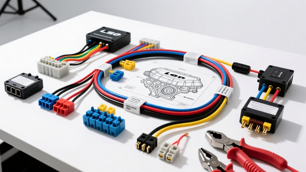
The True Cost of an LS1 Wiring Harness Swap
Executing a Gen III GM V8 transplant into a non-native chassis requires more than just motor mounts and a custom exhaust. The central nervous system of your build relies entirely on accurately interpreting and implementing an ls1 swap wiring diagram. Whether you are dropping a 5.7L LS1 into a classic muscle car, a lightweight track chassis, or an off-road rig, the electrical budget and tooling requirements will dictate the reliability of your build. Cutting corners on wiring materials or using improper crimping tools leads to voltage drops, erratic sensor readings, and catastrophic PCM failures.
Before cutting a single zip tie, builders must decide between modifying a salvaged OEM harness or purchasing a standalone aftermarket unit. Your choice will drastically alter both your financial budget and the specialized tooling required to complete the job.
OEM Harness Modification vs. Standalone Aftermarket
Modifying a factory 1997-2004 F-body or GTO harness is the most cost-effective route, but it demands significant labor. You will need to strip back factory loom, remove emissions-related circuits (like EGR, secondary O2 sensors, and VATS), and extend or shorten wires to fit your new engine bay. Conversely, standalone harnesses from manufacturers like Painless Performance or Holley come pre-loomed, labeled, and stripped of unnecessary emissions circuits, but they command a premium price.
| Cost Category | OEM Harness Repinning | Aftermarket Standalone Harness |
|---|---|---|
| Harness Base Cost | $50 - $150 (Salvage Yard) | $650 - $1,100 (New) |
| Connectors & Terminals | $80 - $120 | $0 (Included) |
| Wire (TXL/GXL) & Loom | $60 - $100 | $0 (Included) |
| Specialized Crimp Tools | $120 - $250 | $40 (Basic crimper) |
| Estimated Labor Time | 15 - 25 Hours | 6 - 10 Hours |
| Total Estimated Budget | $310 - $620 (Plus Labor) | $690 - $1,140 |
Essential Tools for Executing the LS1 Swap Wiring Diagram
To properly modify an OEM harness or extend an aftermarket one, standard hardware store electrical tools will not suffice. Automotive environments subject wiring to extreme heat, vibration, and moisture. According to SAE J1128 standards for low-tension primary cables, automotive wire must resist abrasion and high temperatures, which dictates the use of specific cross-linked insulation wires and precision crimping dies.
Crimpers, Terminals, and Wire Gauges
The GM LS1 PCM and engine sensors utilize Delphi (now Aptiv) Metri-Pack and Weather-Pack connector families. Using a generic crimping tool will deform the terminal tangs, leading to loose pins that vibrate out of the connector housing or create high-resistance connections that trigger false P0101 (MAF) or P0121 (TPS) codes.
- Precision Crimpers: You need a crimper specifically designed for Metri-Pack 150 and 280 series terminals. The OEM Delphi tool (Part #12094430) is ideal, but the Pico 01805-00 or IWISS SN-28B are excellent, budget-friendly alternatives ($40-$80) that yield factory-grade crimps.
- Pin Extraction Tools: A Delphi Metri-Pack extraction tool is mandatory for depinning the bulky 80-way PCM connectors without snapping the fragile plastic retaining barbs.
- Wire Selection: Never use standard PVC wire. Purchase TXL (Thin-wall Cross-Linked) or GXL (General Cross-Linked) wire. TXL is preferred for tight engine bays due to its thinner insulation profile while maintaining a 125°C temperature rating.
- Wire Strippers: Knipex 12 62 180 automatic wire strippers prevent nicking the copper strands, which is critical when working with 18 AWG sensor wires.
Decoding the LS1 PCM Pinout (1999-2002 Gen III)
When referencing your ls1 swap wiring diagram, you will primarily interact with the PCM's two main connectors: C1 (Blue) and C2 (Red). Understanding the critical circuits allows you to prioritize your relay wiring and power distribution blocks. The GM Service Documentation from Helm Inc. remains the gold standard for verifying these pinouts against your specific VIN and calibration.
Critical Sensor and Power Circuits
| Connector | Pin | Circuit Function | OEM Wire Color | AWG Size |
|---|---|---|---|---|
| C1 (Blue) | 20 | Ignition 12V (Crank/Run) | Pink | 14 AWG |
| C1 (Blue) | 1 | MAF Sensor Low | Black | 18 AWG |
| C1 (Blue) | 2 | MAF Sensor High (Signal) | Dark Blue | 18 AWG |
| C1 (Blue) | 57 | Fuel Pump Relay Control | Pink/Black | 18 AWG |
| C2 (Red) | 2 | TPS Signal | Dark Blue | 18 AWG |
| C2 (Red) | 11 | VSS (Vehicle Speed Sensor) | Dark Green | 18 AWG |
| C2 (Red) | 21 | Injector 1 Control | Tan | 14 AWG |
Hidden Costs: Relays, Fuses, and Breakout Boards
A common mistake when budgeting an LS1 swap is forgetting the peripheral components required to support the PCM. The PCM itself should not carry the heavy amperage loads of the fuel pump or cooling fans. It only provides a low-side ground trigger.
- Breakout Boards ($40 - $80): If you are building a harness from scratch or heavily modifying a salvage yard harness, purchasing an LS1 PCM breakout board allows you to solder or crimp pigtails to a solid circuit board rather than struggling with the tiny cavities of the 80-way connector.
- Bosch-Style Relays ($5 - $8 each): You will need a minimum of four 30A/40A SPDT relays: Fuel Pump, Cooling Fan 1, Cooling Fan 2, and Main EFI Power. Ensure you buy sealed, weather-resistant relays with integrated diodes to prevent voltage spikes from frying the PCM driver transistors.
- Waterproof Fuse Holders & Mega Fuses ($35 - $60): The main battery feed to the EFI system requires a 100A to 125A Mega Fuse mounted within 18 inches of the battery positive terminal, utilizing 4 AWG or 2 AWG battery cable.
Expert Troubleshooting & Grounding Protocols
The most frequently overlooked aspect of the ls1 swap wiring diagram is the grounding strategy. The Gen III PCM is incredibly sensitive to ground offsets. If the PCM ground and the engine block ground are at different potentials, the 5-volt reference signals sent to the TPS and MAP sensors will skew, causing erratic idle and timing pull.
The 'Big Three' Grounding Rule
- Engine Block to Chassis: Use a minimum of 4 AWG flexible copper welding cable. Attach it to a clean, unpainted cast-iron surface on the block (such as a bellhousing bolt) and a dedicated chassis stud.
- PCM to Engine Block: The C1 connector (Pins 41, 42, 61, 62) and C2 connector (Pins 1, 2, 3) all terminate to the engine block. Ensure the factory PCM ground ring terminals are sanded clean and bolted directly to the cylinder head or block with star washers to bite through any corrosion.
- Battery to Chassis: The main negative battery cable must have a secondary 4 AWG ground strap routing directly to the chassis frame rail near the battery.
By accurately budgeting for high-grade TXL wire, investing in Delphi-specific crimping tools, and strictly adhering to the grounding protocols outlined in the factory service manuals, your LS1 swap will yield a reliable, factory-quality electrical system capable of handling both daily driving and high-RPM track abuse.