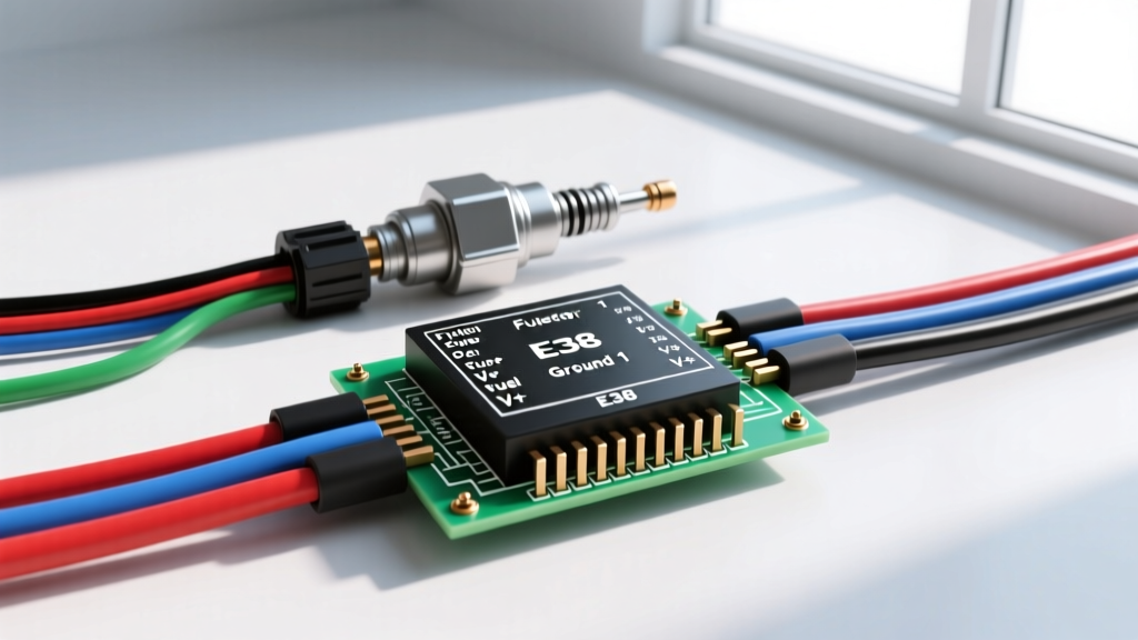
Architecture of the Gen IV LS3 Fuel Injection Circuit
When analyzing a modern powertrain control system, the fuel injector wiring diagram serves as the foundational blueprint for both OEM diagnostics and aftermarket engine swaps. The GM Gen IV LS3 6.2L V8 utilizes a high-impedance, saturated-switch fuel injection architecture. Unlike older peak-and-hold systems that required complex current-limiting resistors or specialized driver circuitry, the LS3’s 42 lb/hr injectors feature an internal coil resistance of approximately 12.5 ohms at 68°F (20°C). This design allows the E38 or E67 Powertrain Control Module (PCM) to use straightforward low-side saturated drivers to ground the circuit, simplifying the harness layout while demanding strict adherence to wire gauge and routing specifications.
Decoding the LS3 Fuel Injector Wiring Diagram
A complete fuel injector wiring diagram for the LS3 platform is divided into two distinct electrical networks: the high-current power feed and the low-current PCM ground control. Understanding the isolation and interaction between these two circuits is critical for diagnosing misfires, injector stuck-open conditions, and PCM driver failures.
Power Feed Network (14 AWG)
The power side of the injector circuit originates at the underhood fuse block. A dedicated 15A or 20A fuse (typically labeled INJ or FUEL INJ) protects the circuit, which is fed by the ignition-controlled run/crank relay. From the fuse, a 14 AWG Pink wire routes to the engine harness. Because the LS3 features eight injectors firing at high duty cycles under load, 14 AWG is mandatory to prevent voltage drop across the parallel splice packs. The 14 AWG Pink wire splits into a series of sealed splice nodes, stepping down to 18 AWG Pink wires at each individual injector connector. Pin 1 of every USCAR injector connector receives this switched 12V reference. During cranking, voltage at Pin 1 should never drop below 9.5V; excessive voltage drop here indicates high resistance in the ignition relay contacts or corroded splice packs.
PCM Ground Control (18 AWG)
Pin 2 of each injector connector is the control circuit, which routes directly back to the PCM. These control wires are 18 AWG, selected for their balance of flexibility in the engine bay and sufficient current-carrying capacity (the peak current draw of a 12.5-ohm injector at 14V is roughly 1.12 amps). The PCM completes the circuit by grounding Pin 2 via an internal Toshiba or Infineon smart low-side driver. These drivers feature built-in thermal shutdown and flyback diode clamping to protect the PCM silicon from the inductive voltage spike generated when the injector coil is de-energized.
ECU Pinout Matrix and OEM Wire Color Codes
Accurate troubleshooting requires cross-referencing the physical harness with the E38 PCM pinout matrix. Below is the standard GM Gen IV LS3 injector control mapping. Note that while the 12V feed is universally Pink, the control wire colors utilize a specific sequence to aid in cylinder identification during bench testing.
| Cylinder | Bank | PCM Connector | PCM Pin | Wire Color (18 AWG) |
|---|---|---|---|---|
| 1 | 1 (Left) | X1 | 15 | Dark Green |
| 2 | 1 (Left) | X1 | 16 | Dark Blue |
| 3 | 1 (Left) | X1 | 17 | Brown |
| 4 | 1 (Left) | X1 | 18 | Gray |
| 5 | 2 (Right) | X2 | 19 | Yellow |
| 6 | 2 (Right) | X2 | 20 | Purple |
| 7 | 2 (Right) | X2 | 21 | Tan |
| 8 | 2 (Right) | X2 | 22 | Light Blue |
Note: Always verify pinouts against the specific GM Service Information (GMSI) schematic for your exact VIN, as mid-year harness revisions can alter connector cavity assignments.
USCAR Connector Specifications vs. Legacy EV1/EV6
A common pitfall when interpreting a fuel injector wiring diagram for LS-based engines is misidentifying the connector standard. The LS3 utilizes the USCAR 2-pin standard, not the legacy Bosch EV1 (Jetronic) or EV6 connectors found on older 90s platforms. The USCAR connector features a wider terminal spacing, a robust external metal locking clip, and an integrated secondary latch. The terminals are specifically designed to maintain high normal force (contact pressure) to withstand the high-frequency vibrations of a pushrod V8. When repairing a USCAR pigtail, always use the correct crimp die for the USCAR terminal width; forcing an EV6 terminal into a USCAR housing will result in a loose fit, leading to intermittent open circuits and random misfire codes (P0300 series).
Advanced Oscilloscope Diagnostics: The Injector Waveform
Visual inspection of the fuel injector wiring diagram only reveals the static path of the circuit. To evaluate dynamic health, an automotive oscilloscope is mandatory. By back-probing the PCM control wire (18 AWG) with the engine running, you can capture the saturated switch waveform, which is divided into distinct diagnostic phases.
Phase 1: Pull-In and Holding Current
When the PCM commands the injector open, the low-side driver pulls the 18 AWG control wire to ground. On the scope, the voltage drops from the 14V baseline to near 0V (typically 0.2V to 0.5V, representing the internal voltage drop of the PCM driver transistor). The current ramps up rapidly, generating the magnetic field required to lift the injector pintle. Once the pintle is seated open, the PCM maintains the ground path. The voltage remains flat at the driver's saturation voltage for the duration of the commanded pulse width.
Phase 2: Inductive Kick and Flyback Clamping
The most critical diagnostic event occurs when the PCM removes the ground to close the injector. The collapsing magnetic field in the injector coil induces a massive reverse voltage spike (Lenz's Law). Without protection, this spike could exceed 200V and instantly destroy the PCM's internal driver. As detailed in MotorAge's injector waveform analysis, the PCM's internal flyback diode clamps this inductive kick to a safe threshold, typically between 50V and 75V. On your oscilloscope, this appears as a sharp vertical spike immediately followed by a rapid decay and a series of diminishing oscillations (ringing) as the residual energy dissipates through the coil's internal resistance. If the clamping voltage is missing or exceeds 90V, the internal flyback diode has failed, and the PCM is at imminent risk of catastrophic damage.
Common Failure Modes and PCM Driver Protection
Understanding the wiring diagram allows technicians to isolate the root cause of injector-related failures. The most frequent real-world failure mode on the LS3 platform is harness chafing. The engine harness routes tightly against the rear of the cylinder heads and the firewall. Over time, vibration wears through the 18 AWG wire loom, exposing the copper. If a control wire (e.g., the Dark Green wire for Cylinder 1) shorts directly to the engine block (ground), the injector will remain stuck open, flooding the cylinder and washing the oil off the cylinder walls, leading to catastrophic hydro-lock or bore scoring.
Furthermore, if an aftermarket injector with a low-impedance coil (e.g., 2.5 ohms) is installed without an external ballast resistor or a peak-and-hold controller, the current draw will exceed 5 amps. The E38 PCM's saturated drivers are not designed for this thermal load. The smart driver will detect the over-current condition and trigger an internal thermal shutdown, logging a P020X code and disabling the injector circuit to prevent a PCM fire. Always verify injector impedance with a multimeter before plugging unknown components into an OEM harness; Delphi Technologies recommends confirming a 12.0 to 13.0 ohm reading across the USCAR terminals for all standard GM Gen IV high-impedance applications.
Summary of Diagnostic Best Practices
- Voltage Drop Testing: Perform a loaded voltage drop test on the 14 AWG Pink power feed. A drop greater than 0.5V across the fuse block to the injector splice pack indicates corroded bulkhead connectors.
- Resistance Verification: Measure injector coil resistance at the PCM connector pins (e.g., X1 Pin 15 to chassis ground) to verify the integrity of the entire 18 AWG control wire and the internal injector coil simultaneously.
- Terminal Tension: Use a dedicated USCAR terminal test pick to verify locking tab engagement. A loose terminal will cause a high-frequency misfire that only appears above 4,500 RPM due to harmonic engine vibration.