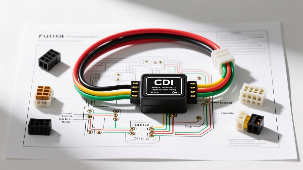
Understanding the Core Components of Motorcycle Ignition
For many beginner mechanics and custom bike builders, staring at a simple motorcycle ignition wiring diagram can feel like trying to read a foreign language. However, motorcycle electrical systems—particularly on single-cylinder and twin-cylinder machines—are remarkably straightforward compared to modern automotive CAN-bus networks. To master the diagram, you must first understand the physical components it represents and the path the electrical current takes to create a spark.
A standard Capacitor Discharge Ignition (CDI) system relies on five primary components:
- Stator (Source Coil): Mounted behind the engine flywheel, this coil generates raw alternating current (AC) voltage, often stepping up to 100V-400V depending on engine RPM.
- Pulser Coil (Pickup): A magnetic sensor that reads the passing flywheel reluctor tooth, sending a low-voltage timing signal to the ignition brain.
- CDI Unit: The capacitor bank and thyristor switch that stores high voltage and releases it in a microsecond burst.
- Ignition Coil: A transformer that steps the CDI's output voltage up from roughly 200V to 20,000V–40,000V.
- Spark Plug: The final electrode gap where the high-voltage arc ignites the air/fuel mixture.
When you look at a schematic, you are simply tracing the bridges between these five islands. Understanding this flow transforms a confusing web of lines into a logical sequence of events.
Deconstructing the Schematic: Visual Language and Flow
A proper simple motorcycle ignition wiring diagram uses standardized symbols. A zig-zag line represents a coil (stator or ignition), a box with a diagonal arrow represents the CDI thyristor, and a dashed line crossing a solid line usually denotes a spark gap. Current flow is typically read from left to right, or from the power source (stator/battery) at the top down to the ground at the bottom.
Standard Wire Color Codes and AWG Specifications
While European and American manufacturers have their own quirks, Japanese motorcycles (Honda, Yamaha, Suzuki, Kawasaki) established a universal color code standard that most aftermarket and Chinese-manufactured clone engines still follow today. Adhering to these colors and selecting the correct American Wire Gauge (AWG) is critical to preventing voltage drop and heat-induced failures.
According to the SAE J1128 standard for Low Tension Primary Cables, wire insulation must withstand under-hood temperatures and chemical exposure. Always use stranded copper wire, never solid core, as engine vibration will quickly snap solid wire.
| Wire Color | Function | Recommended AWG | Typical Voltage / Signal |
|---|---|---|---|
| Black / Yellow | Stator Source Coil to CDI | 18 AWG | 100V - 400V AC |
| Blue / White | Pulser Coil Positive (+) | 20 AWG | 0.5V - 3V AC Pulse |
| Green / White | Pulser Coil Negative (-) | 20 AWG | Signal Ground |
| Black / White | Kill Switch / Ground Out | 18 AWG | 12V / Ground Path |
| Orange / Black | CDI Output to Ignition Coil | 18 AWG | 200V - 400V DC Spike |
| Red | 12V DC Main Power (DC CDI) | 16 AWG | 12V - 14.4V DC |
| Black / Green | Chassis Ground | 14 AWG | 0V Reference |
Step-by-Step Wiring: 6-Pin CDI Unit Pinout
The most common ignition brain found in small displacement motorcycles, ATVs, and dirt bikes is the 6-pin DC CDI. If your simple motorcycle ignition wiring diagram features a 6-pin rectangular connector, you can map it using the following industry-standard pinout. Always verify with a multimeter, as some obscure aftermarket units may swap pins 3 and 4.
- Pin 1 (Red): 12V DC Input. Connects to the ignition switch. This powers the internal oscillator and charging circuit of the CDI.
- Pin 2 (Black/Green): Main Ground. Must be routed directly to the engine block or battery negative. A poor ground here causes weak spark and erratic timing.
- Pin 3 (Blue/White): Pulser Positive. Connects to the pickup coil's positive output.
- Pin 4 (Green/White): Pulser Negative. Connects to the pickup coil's negative output.
- Pin 5 (Black/White): Kill Switch. This is a normally-open circuit. When the kill switch is pressed, it bridges this pin to ground, shorting the internal capacitor and halting the spark.
- Pin 6 (Orange/Black): High Voltage Output. Routes directly to the primary positive terminal of the ignition coil.
AC vs. DC CDI Systems: Identifying Your Setup
One of the most frequent beginner mistakes is installing a DC CDI on an AC stator system, or vice versa. Your wiring diagram will give you the answer immediately.
The AC CDI Configuration
In an AC system, the motorcycle does not need a battery to run. The wiring diagram will show a wire (usually Black/Yellow) running directly from the stator's dedicated source coil into the CDI. The CDI internally rectifies and steps up this raw AC voltage to charge its capacitor. If your diagram lacks a 12V battery feed wire to the CDI, you have an AC system.
The DC CDI Configuration
A DC CDI relies on the motorcycle's 12V battery and stator lighting/charging coil to supply power. The wiring diagram will show a Red wire running from the ignition switch (battery positive) into the CDI. The CDI uses an internal DC-to-DC step-up transformer to generate the 200V+ needed for the spark. DC CDIs provide a hotter, more consistent spark at low cranking RPMs, which is why they are preferred for custom builds and cold-weather starting.
Real-World Troubleshooting: Multimeter Diagnostics
When the engine cranks but refuses to fire, the wiring diagram becomes your diagnostic map. Instead of throwing parts at the bike, use a digital multimeter to test the circuit nodes. According to Haynes Motorcycle Repair Manuals, isolating the fault requires checking resistance (Ohms) at specific checkpoints.
Diagnostic Decision Tree: No Spark Condition
- Check the Kill Switch Circuit: Set the multimeter to continuity. Probe the Black/White wire at the CDI connector. With the key ON and the kill switch set to RUN, there should be infinite resistance (OL) to ground. If you read 0 ohms, your kill switch is shorted or the wiring is pinched against the frame.
- Test the Pulser Coil: Disconnect the stator plug. Measure the resistance across the Blue/White and Green/White wires. A healthy pulser coil typically reads between 100 and 250 ohms. A reading of 0 indicates a short; infinite indicates a broken internal winding.
- Test the Stator Source Coil (AC Systems Only): Measure the Black/Yellow wire to ground. You should see a resistance between 100 and 500 ohms. Furthermore, set the multimeter to AC Voltage and crank the engine; you should see a minimum of 15V-30V AC generated at cranking speeds.
- Verify the Ignition Coil: The ignition coil has two circuits. The primary circuit (the two small spade terminals) should read between 0.5 and 2.0 ohms. The secondary circuit (measured from the primary positive terminal to the spark plug boot contact) should read between 10,000 and 30,000 ohms (10k-30kΩ). If the secondary resistance is wildly out of spec, the internal copper windings have failed, and the coil must be replaced.
Connector Types and Best Practices
A simple motorcycle ignition wiring diagram assumes perfect connections, but the reality of a motorcycle's operating environment involves severe vibration, water intrusion, and thermal cycling. Never use twist-on wire nuts or standard electrical tape for ignition circuits.
For stator-to-harness connections, use Delphi Weather-Pack or Deutsch DT connectors. These feature silicone rubber seals that prevent moisture ingress and corrosion on the copper strands. For the high-voltage output wire running from the CDI to the ignition coil, use a dedicated JST SM or molded rubber boot connector to prevent the 30,000V secondary arc from jumping to the chassis. Always apply a dab of dielectric grease to the connector pins before mating them, and use adhesive-lined marine heat shrink on all crimp terminals to seal out oxygen and prevent green rot.
By understanding the fundamental flow of current, respecting AWG sizing limits, and methodically testing nodes with a multimeter, you can confidently read, build, and troubleshoot any simple motorcycle ignition wiring diagram you encounter.