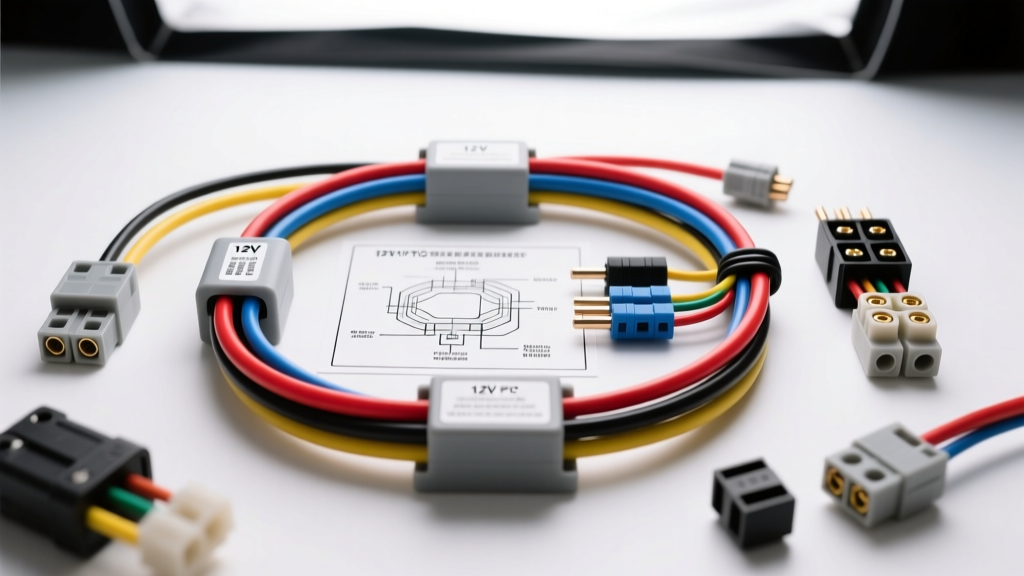
Introduction to 12V Automotive Electric Heaters
When the temperature drops, an auxiliary 12V cabin heater can be a lifesaver for off-road SUVs, work trucks, and RVs. Modern aftermarket heaters utilize PTC (Positive Temperature Coefficient) heating elements, which are highly efficient, self-regulating, and lack the open coils found in older, dangerous models. However, because these devices draw significant current, understanding a proper electric heater wiring diagram is critical to prevent melted wires, blown fuses, or electrical fires.
This beginner-friendly guide breaks down the fundamentals of wiring a 12V PTC heater (typically rated between 150W and 300W). Safety Note: This guide applies strictly to 12V auxiliary systems. If you are working on an Electric Vehicle (EV) or Hybrid, never touch the high-voltage HVAC system, which is easily identified by bright orange cabling and requires certified high-voltage training.
Decoding the Electric Heater Wiring Diagram
The most common mistake beginners make is wiring the heater directly to a dashboard switch. A 200W PTC heater draws roughly 16.6 amps continuously. Standard dashboard toggle switches are rated for 10A to 15A at best; routing 16+ amps through them will cause the switch to melt. Therefore, every safe electric heater wiring diagram utilizes a Bosch-style automotive relay to separate the high-current power circuit from the low-current switching circuit.
The 4-Pin Relay Schematic Breakdown
- Pin 30 (Power In): Receives direct 12V power from the vehicle battery via a main inline fuse.
- Pin 87 (Power Out): Sends 12V power to the positive terminal of the PTC heater when the relay is energized.
- Pin 86 (Trigger In): Receives a low-current 12V signal from your dashboard switch (which is powered by an ignition-switched fuse).
- Pin 85 (Trigger Ground): Provides the ground path for the relay's internal electromagnet coil.
Component Specifications and Wire Sizing Chart
Adhering to the SAE International J1128 Standard for low-tension primary cable ensures your wiring can handle the thermal load. Below is the specification chart for a standard 200W (16.6A nominal) PTC heater installation.
| Circuit Segment | Wire Gauge (AWG) | Standard Color Code | Max Ampacity / Component |
|---|---|---|---|
| Battery to Relay (Pin 30) | 12 AWG | Red | 25A Inline ATO Fuse |
| Relay (Pin 87) to Heater (+) | 12 AWG | Red | 20A Continuous |
| Heater (-) to Chassis Ground | 12 AWG | Black | M6 Ring Terminal |
| Ignition Source to Dashboard Switch | 16 AWG | Yellow | 5A Fuse (Tap) |
| Switch to Relay (Pin 86) | 16 AWG | Blue | 1A - 2A Draw |
| Relay (Pin 85) to Chassis Ground | 16 AWG | Black | M5 Ring Terminal |
Step-by-Step Wiring Fundamentals
Step 1: Sizing the Fuse and Battery Connection
Always disconnect the negative battery terminal before beginning work. PTC heaters experience an "inrush current" when cold. Because resistance is lower before the element heats up, a 16.6A heater can momentarily pull up to 25A upon startup. To accommodate this without nuisance blowing, use a 30A standard blade (ATO) fuse or a 25A slow-blow fuse located within 18 inches of the battery positive terminal. Route the 12 AWG red wire through the firewall using an existing rubber grommet to prevent chafing.
Step 2: Wiring the Relay and Switch
Mount a standard 12V 30A/40A Bosch-style relay in a dry area under the dash or in the engine bay. Connect the 12 AWG power wire to Pin 30. Run a 16 AWG yellow wire from an ignition-switched fuse (using an Add-A-Circuit fuse tap) to your dashboard toggle switch. From the switch, run a 16 AWG blue wire to Pin 86 on the relay. This ensures the heater can only be turned on when the key is in the "ON" or "ACC" position, preventing a dead battery if you forget to turn it off.
Step 3: Grounding the PTC Element
A poor ground is the number one cause of automotive electrical failure. Do not simply screw the ground wire into painted sheet metal. Locate a solid chassis bolt, remove it, and sand the contact area down to bare, shiny metal using 80-grit sandpaper. Attach a 12 AWG black wire with a 1/4" ring terminal to the heater's negative lead, and secure it to the chassis using the original bolt and a star washer. For optimal conductivity and corrosion resistance, apply a dab of dielectric grease over the terminal after torquing the bolt to 10 Nm (88 in-lbs).
Understanding PTC Inrush Current and Fuse Selection
According to TDK Electronics PTC Thermistor Fundamentals, the self-regulating nature of PTC ceramics means that as the element reaches its target temperature, its electrical resistance increases exponentially, naturally tapering off the current draw. However, the initial cold-state resistance is low. If your electric heater wiring diagram specifies a standard fast-acting fuse, the 1.5x inrush spike will blow the fuse immediately upon flipping the switch. Always opt for time-delay (slow-blow) fuses for inductive or high-inrush resistive loads like PTC heaters, window motors, and fuel pumps.
Troubleshooting Common Wiring Faults
Even with a perfect diagram, real-world installations encounter issues. Use this diagnostic tree to solve common problems:
- Symptom: Relay clicks, but heater blows cold air.
Cause: Voltage drop on the power or ground side. The PTC element requires a minimum of 11.5V to generate heat. Use a multimeter to measure voltage directly at the heater terminals while the circuit is active. If you read 9V or 10V, your 12 AWG wire is too long, or your ground connection has high resistance due to paint or rust. - Symptom: Fuse blows instantly upon switching on.
Cause: Dead short. Check the 12 AWG red wire between the relay (Pin 87) and the heater. It is likely pinched against a metal bracket or the firewall grommet was improperly routed, exposing bare copper to the chassis. - Symptom: Heater works, but dashboard switch gets hot.
Final Thoughts on Electrical Safety
Mastering the fundamentals of an electric heater wiring diagram empowers you to add high-draw accessories safely. Always use ratcheting crimpers for your terminals—pliers do not provide the necessary cold-weld compression and will vibrate loose over time. By respecting wire gauge limits, utilizing relays for load switching, and ensuring pristine chassis grounds, your auxiliary heater will provide reliable warmth for years to come.