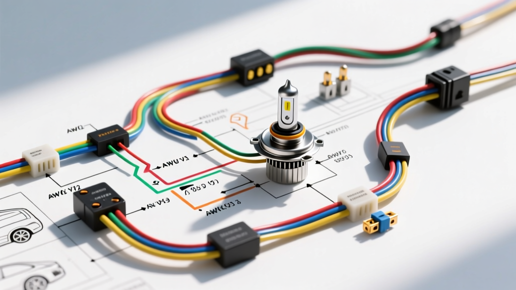
Decoding the Simple Car Wiring Diagram
While modern vehicles rely on complex multiplexed CAN-bus networks and body control modules (BCMs), mastering a simple car wiring diagram remains the foundational skill for any automotive technician or DIY enthusiast. Every complex electrical fault ultimately traces back to basic principles: power sources, control switches, loads, and grounds. By breaking down a universal, high-current circuit—such as an aftermarket H4 halogen headlight relay upgrade—we can establish a mental framework for reading any automotive schematic.
In this complete wiring diagram walkthrough, we will trace a standard 12V DC headlight circuit from the battery positive terminal to the chassis ground. We will cover SAE J1128 Low Voltage Cable Standard color codes, American Wire Gauge (AWG) sizing, ISO relay pinouts, and real-world diagnostic strategies that separate amateur guessers from professional auto-electricians.
Anatomy of an H4 Headlight Relay Circuit
Factory headlight wiring in older vehicles often routes full headlight current through the dashboard switch and the multifunction turn signal stalk. This causes severe voltage drop, resulting in dim lights and melted switch contacts. A proper upgrade utilizes a simple car wiring diagram centered around a standard Bosch-style ISO 4-pin relay to handle the heavy load.
1. The Power Feed (Battery to Relay)
The circuit begins at the battery positive terminal. A main power wire runs to a fuse block, then to the relay. Because an H4 bulb draws approximately 55 watts on low beam and 60 watts on high beam (roughly 4.5 to 5.0 amps per bulb), a dual-headlight setup pulls 10 amps continuously, with a higher initial inrush current when the cold tungsten filaments are first energized.
- Wire Size: 12 AWG stranded copper (rated for 20A in engine bay heat).
- SAE Color Code: Red (RD).
- Protection: 20A ATO blade fuse located within 18 inches of the battery positive terminal.
- Termination: Ring terminal on a 6mm or 8mm stud, secured with a star washer to bite through surface corrosion.
2. The Control Circuit (Switch to Relay Coil)
The control circuit uses low current to trigger the relay's electromagnetic coil. The factory headlight switch now only powers the relay coil, protecting the delicate dashboard wiring.
- Switched Power (Pin 86): 16 AWG Yellow (YEL) wire runs from the factory headlight switch output to Pin 86 on the ISO relay.
- Relay Coil Ground (Pin 85): 16 AWG Black (BLK) wire runs from Pin 85 to a clean, bare-metal chassis ground point.
- Coil Resistance: A standard 12V ISO relay coil measures between 65 and 85 ohms. If your multimeter reads infinite resistance (OL), the internal coil is burnt open.
3. The Load Path (Relay to Bulb)
When the coil is energized, the internal armature pulls the high-current contacts closed, linking Pin 30 to Pin 87.
- Relay Input (Pin 30): Connected to the fused 12 AWG Red battery feed.
- Relay Output (Pin 87): 12 AWG Blue (BLU) wire carries the full 10A+ load directly to the H4 bulb connector.
- Load Ground: The H4 bulb base grounds directly to the chassis via a 12 AWG Black (BLK) wire. Never rely on the bulb housing or mounting tabs for a primary ground path; always run a dedicated ground wire to a verified clean chassis point.
SAE J1128 Wire Color Codes and AWG Sizing
When reading a simple car wiring diagram, understanding standardized color codes and gauge limits is critical for both safety and diagnostics. The SAE J1128 standard dictates insulation thickness, temperature ratings, and color abbreviations for automotive primary wire.
| AWG Size | Max Ampacity (Engine Bay) | Typical Application | Common SAE Colors |
|---|---|---|---|
| 18 AWG | 6 Amps | ECU sensors, low-current signal wires, LED indicator lights | White (WT), Light Green (LT GRN) |
| 16 AWG | 10 Amps | Relay coil control circuits, horn triggers, wiper switch signals | Yellow (YEL), Purple (PPL) |
| 14 AWG | 15 Amps | Tail lights, interior dome lights, fuel pump feeds | Brown (BRN), Dark Blue (DK BLU) |
| 12 AWG | 20 Amps | Headlights, power windows, blower motor circuits | Red (RD), Blue (BLU) |
| 10 AWG | 30 Amps | Main ignition feeds, high-current cooling fan relays, ABS pumps | Red (RD) with Black (BLK) stripe |
Real-World Troubleshooting Using the Schematic
A wiring diagram is not just a map for building circuits; it is a diagnostic decision tree. According to Autoshop 101 Electrical Fundamentals, the most accurate way to diagnose a failing simple car wiring diagram is through live-circuit voltage drop testing, rather than static continuity testing.
Step 1: The Voltage Drop Test
Set your digital multimeter (DMM) to DC Volts. Turn the headlights ON to place the circuit under load. Place the red probe on the battery positive post and the black probe on the relay Pin 30 input terminal. A healthy circuit will show less than 0.10V drop. If you read 0.50V or higher, you have high resistance—likely a corroded fuse holder or a failing crimp connection.
Step 2: Verifying the Ground Path
Place the red DMM probe on the battery negative post and the black probe on the H4 bulb ground terminal (with lights ON). Again, the reading must be below 0.10V. A reading of 1.5V indicates that current is struggling to return to the battery, often due to rust under the ground ring terminal. This manifests as dim lights and can cause back-feeding through other circuits (a phenomenon known as a "floating ground").
Step 3: Relay Auditory and Thermal Checks
When the switch is actuated, the relay should emit a sharp, distinct click. If it buzzes or chatters, the control circuit voltage is too low (often below 10.5V at Pin 86), or the internal armature spring is failing. Furthermore, touch the relay casing after 10 minutes of operation. It should be warm, but not hot. A relay casing exceeding 140°F (60°C) indicates internal contact pitting and excessive resistance across Pins 30 and 87.
Connector Selection and Termination Best Practices
The most common failure point in any simple car wiring diagram execution is poor termination. Soldering wire in an automotive environment is heavily discouraged by OEM engineering standards. Solder creates a rigid, brittle joint that will eventually fracture under the constant high-frequency vibration of a vehicle chassis. Furthermore, solder wicks under the wire insulation via capillary action, trapping moisture and accelerating galvanic corrosion.
Use Weather-Sealed Connectors
For under-hood applications like headlight circuits, always use weather-sealed connector systems such as the Delphi Weather-Pack or Metri-Pack 280 series. These connectors feature silicone ribbed seals that compress around the wire insulation, preventing water and road salt intrusion.
Proper Crimping Technique
Use an open-barrel or closed-barrel ratcheting crimper specific to the terminal type. A proper crimp deforms the terminal wings around the wire strands, creating a cold-weld (gas-tight connection) where oxygen cannot reach the copper to cause oxidation. After crimping, perform a pull-test: the wire should break before the crimp fails. Always apply a small dab of dielectric grease inside the connector cavity before mating the halves to displace moisture and prevent terminal fretting corrosion.
Common Failure Modes in Simple Lighting Circuits
Even when built perfectly, simple circuits face harsh environmental realities. Referencing Hella Lighting Technology Guidelines, understanding how loads interact with wiring helps predict failures.
- Thermal Cycling Fatigue: H4 bulbs generate immense heat. The plastic 3-prong H4 connector (often made of low-grade Bakelite or nylon) can become brittle and melt over time. Upgrading to a ceramic H4 pigtail is highly recommended for circuits drawing over 55W.
- Relay Diode Flyback: If your simple car wiring diagram interfaces with a modern vehicle's ECU or body control module, you must use a relay with an internal suppression diode or resistor. When the relay coil is de-energized, the collapsing magnetic field generates a high-voltage reverse spike (flyback voltage) that can instantly fry sensitive solid-state ECU drivers.
- Stranded Wire Fraying: When stripping 12 AWG stranded wire, using standard pliers often nicks the outer copper strands, reducing the effective cross-sectional area and creating a localized hot spot. Always use precision wire strippers calibrated to the specific AWG.
Conclusion
Mastering a simple car wiring diagram is about understanding the relationship between current flow, resistance, and component protection. By correctly sizing your AWG wire, adhering to SAE color codes, utilizing ISO relays to protect delicate switches, and executing gas-tight crimp terminations, you ensure a lighting circuit that is both brilliantly bright and reliably safe for the life of the vehicle. Keep your multimeter handy, trust the voltage drop test over a simple continuity check, and always verify your grounds.