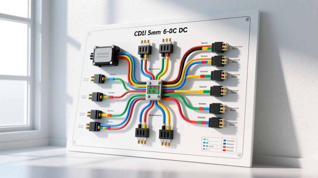
Introduction to Capacitor Discharge Ignition (CDI) Architecture
The Capacitor Discharge Ignition (CDI) system remains a cornerstone of small engine, motorcycle, ATV, and racing automotive electrical architectures. Unlike traditional inductive ignition systems that rely on the slow saturation and sudden collapse of an ignition coil's magnetic field, a CDI system stores high-voltage energy in a capacitor and discharges it almost instantaneously through a Silicon Controlled Rectifier (SCR) into the ignition coil. This results in an extremely fast voltage rise time (high dV/dt), which is critical for igniting lean air-fuel mixtures and resisting spark plug fouling under heavy cylinder pressures.
When sourcing or troubleshooting a wiring diagram for CDI box applications, technicians must first identify whether the system is an AC-CDI or a DC-CDI. AC-CDI systems draw power directly from a dedicated high-voltage stator source coil (typically 100V to 400V AC), which is rectified and stored in the internal capacitor. DC-CDI systems, conversely, utilize the vehicle's 12V battery and employ an internal DC-DC boost converter to step the voltage up to the required 300V-400V threshold. Understanding this distinction is paramount, as miswiring a DC-CDI to an AC stator source will instantly destroy the internal boost circuitry.
Internal Topology and Component Specifications
Before tracing external harnesses, it is vital to understand the internal topology of the CDI box. The core energy storage component is typically a metalized polypropylene film capacitor rated between 1.0µF and 2.2µF at 400V-600V DC. The switching mechanism is a high-voltage, high-current SCR (thyristor). When the trigger coil sends a low-voltage pulse (usually 2V to 5V) to the SCR's gate, the thyristor latches into a conductive state, dumping the capacitor's stored charge into the primary winding of the ignition coil in approximately 50 to 100 microseconds. This rapid discharge induces a massive flyback voltage in the coil's secondary winding, generating a spark of 30,000V to 45,000V.
6-Pin AC-CDI Box Wiring Diagram & Pinout Table
The 6-pin AC-CDI is the most ubiquitous configuration found on Honda, Kawasaki, Yamaha, and generic GY6/Lifan engines ranging from 50cc to 250cc. The connector is typically a 6-cavity nylon block utilizing 2.8mm unsealed female spade terminals. Below is the definitive pinout, wire color code, and AWG specification for the standard OEM 6-pin AC-CDI.
| Pin | Function | Standard OEM Wire Color | Recommended AWG | Circuit Notes & Specifications |
|---|---|---|---|---|
| 1 | Chassis Ground | Green or Black | 14 - 12 AWG | Must have less than 0.05 ohms resistance to the engine block. Critical for SCR commutation. |
| 2 | Engine Kill Switch | Black/White | 18 AWG | Grounds the trigger circuit or capacitor charge. 0V = Kill, Open = Run. |
| 3 | Pulse / Trigger Coil | Blue/Yellow or White | 20 - 18 AWG | Receives 2V-5V AC pulse from the stator pickup. Do not route parallel to spark plug wires. |
| 4 | AC Source Coil | Red/Black or Pink | 16 - 14 AWG | High voltage AC input (100V-400V). Requires robust insulation and secure crimp connections. |
| 5 | To Ignition Coil | Black/Yellow | 16 AWG | High-voltage DC discharge to the coil primary. Keep wire length under 18 inches to reduce parasitic inductance. |
| 6 | Lighting / NC | Yellow or Empty | N/A | Often used for tachometer signal or left unpopulated in pure racing applications. |
5-Pin DC-CDI Box Wiring Diagram & Pinout Table
The 5-pin DC-CDI is common on modern street-legal motorcycles and ATVs where stator output is strictly regulated for battery charging, leaving no dedicated high-voltage AC coil for ignition. The DC-CDI relies on a stable 12V DC supply. If battery voltage drops below 9.5V during cranking, the internal DC-DC converter will fail to reach the 350V capacitor threshold, resulting in a no-spark condition.
| Pin | Function | Standard OEM Wire Color | Recommended AWG | Circuit Notes & Specifications |
|---|---|---|---|---|
| 1 | 12V DC Power | Red or Black/Red | 14 AWG | Must be switched via the ignition relay. Requires a clean 12V+ source capable of 4A peak draw. |
| 2 | Chassis Ground | Green or Black | 12 AWG | Heavy ground required to handle the return current of the DC-DC boost converter. |
| 3 | Trigger / Pickup | Blue or Blue/Yellow | 20 AWG | Low voltage signal from the Hall effect or magnetic pickup sensor. |
| 4 | Engine Kill Switch | Black/White | 18 AWG | Grounds the internal logic board to cease firing. |
| 5 | To Ignition Coil | Black/Yellow | 16 AWG | Primary discharge output. Connect directly to the coil's positive terminal. |
Stator Source Coil & Trigger Testing Specifications
When using a wiring diagram for CDI box troubleshooting, the most common point of failure is not the CDI itself, but the stator coils feeding it. Before condemning a CDI unit, you must verify the stator outputs using a digital multimeter (DMM) and an oscilloscope. According to Haynes Motorcycle Repair Manuals, testing must be done at the stator connector with the CDI disconnected to eliminate parallel circuit interference.
| Component | Resistance (Ohms) | Peak AC Voltage (Cranking) | Peak AC Voltage (3000 RPM) |
|---|---|---|---|
| AC Source Coil | 100 - 400 Ω | 15V - 30V AC | 80V - 150V AC |
| Trigger / Pulse Coil | 70 - 150 Ω | 0.5V - 1.5V AC | 3.0V - 6.0V AC |
| Ignition Coil Primary | 0.1 - 0.5 Ω | N/A | N/A |
| Ignition Coil Secondary | 8,000 - 15,000 Ω | N/A | N/A |
High-Performance Racing CDI Integration (MSD 6AL)
For advanced automotive and racing applications, aftermarket units like the MSD 6AL series operate on similar capacitive discharge principles but require vastly different wiring protocols. As detailed in the MSD Performance Wiring Diagrams, these units feature multiple spark discharge capabilities below 3,000 RPM. Wiring an MSD 6AL requires heavy 8 AWG battery cables for the main power and ground to support the massive current draw during multi-spark sequences. The magnetic pickup trigger relies on a twisted pair of Violet (signal) and Green (ground) wires, which must be kept away from high-tension ignition wires to prevent electromagnetic interference (EMI) from inducing false trigger gates.
Oscilloscope Diagnostics & Real-World Failure Modes
Advanced diagnostics require looking beyond simple resistance checks. Connecting an oscilloscope to the trigger wire and the primary coil wire reveals the health of the CDI's internal SCR and capacitor. A healthy CDI will show a sharp, vertical voltage spike on the primary coil trace, followed by a rapid decay. If the capacitor is degraded (often visible physically as a bulging or leaking epoxy potting compound), the spark duration will elongate, and peak voltage will drop significantly.
Common real-world failure modes include:
- Shorted SCR: The CDI continuously dumps the capacitor as soon as the stator generates voltage. Symptoms include backfiring through the carburetor, kickstarter lock-up due to premature ignition timing, and eventual stator burnout.
- Leaky Internal Rectifier Diode: Allows AC ripple to reach the ignition coil, resulting in a weak, yellow spark rather than a crisp blue spark. The engine will idle poorly and misfire under load.
- Parasitic Inductance in Harness: Using wire gauges that are too thick or routing the Black/Yellow coil wire in tight coils creates inductance, which opposes the rapid dI/dt of the capacitor discharge, effectively choking the spark energy.
For deeper circuit-level analysis and schematic breakdowns of the internal thyristor switching networks, refer to the comprehensive ElectroSchematics CDI Circuit Analysis. Proper integration of any CDI system demands strict adherence to wire gauge specifications, meticulous grounding, and an understanding of the high-voltage dynamics at play within the capacitor discharge cycle.