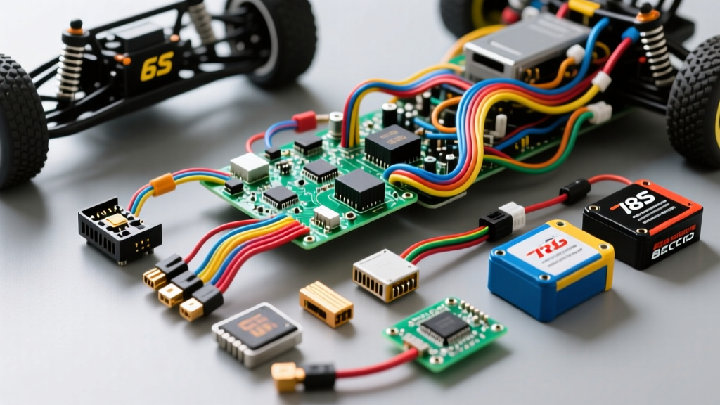
Phase 1: Main Power Distribution and ESC Integration
The foundation of any robust rc car wiring schematic begins at the high-current battery leads. For a 1/8 scale 6S platform, 10 AWG silicone-insulated wire is the absolute minimum specification. Unlike standard PVC automotive wire governed by SAE J1128 standards, high-strand-count silicone wire (typically 1050 strands of 30 AWG tinned copper) provides the flexibility needed for chassis articulation while mitigating the skin effect at the high PWM switching frequencies (16kHz to 32kHz) generated by the Electronic Speed Controller (ESC).The physical length of the wire between the battery connector (typically an XT90 or IC5) and the ESC input terminals must be kept under 18 inches. Exceeding this length increases parasitic inductance, which can cause voltage spikes that exceed the drain-source breakdown voltage (Vdss) of the ESC's internal MOSFETs, leading to catastrophic failure.
AWG and Current Capacity Reference Chart
| Wire Gauge (AWG) | Strand Count (30 AWG) | Continuous Current (A) | Burst Current (A) | Application in RC Schematic |
|---|---|---|---|---|
| 8 AWG | 1650 | 180A | 280A | 1/5 Scale Main Battery Leads, 8S Platforms |
| 10 AWG | 1050 | 120A | 200A | 1/8 Scale Main Battery Leads, 6S Platforms |
| 12 AWG | 650 | 80A | 140A | Motor Phase Wires (ESC to Brushless Motor) |
| 16 AWG | 260 | 30A | 50A | Standalone Receiver Battery Leads |
| 22 AWG | 65 | 5A | 9A | BEC Outputs, Servo Power Rails |
Phase 2: The Receiver and BEC (Battery Eliminator Circuit) Schematic
In high-voltage schematics, the BEC is a critical node. A linear BEC dropping 22.2V down to a 6.0V receiver rail at 3 amps would dissipate nearly 50 watts of heat, instantly destroying the component. Therefore, the schematic must specify a Switching BEC (SBEC) or a standalone 2S LiFePO4 receiver pack.When wiring an SBEC into the receiver hub, the red (V+) and black (GND) wires are routed to Channel 3 or a dedicated BAT port, while the signal wire is often omitted or capped unless the ESC requires a specific telemetry handshake. The ground plane must be shared continuously; a floating ground between the ESC SBEC and the steering servo will result in erratic PWM signal interpretation, causing the steering servo to twitch or lock at full throw.
Standard 6-Channel Telemetry Receiver Pinout
| Channel / Port | Pin 1 (Signal) | Pin 2 (V+) | Pin 3 (GND) | Function & Wiring Notes |
|---|---|---|---|---|
| CH 1 (Steering) | Orange / Yellow | Red (6.0V - 8.4V) | Black / Brown | High-Voltage Steering Servo PWM Input |
| CH 2 (Throttle) | Orange / Yellow | Red (Disabled) | Black / Brown | ESC Throttle Signal (V+ pin often removed to prevent backfeed) |
| CH 3 (Aux/BEC) | None | Red (6.0V Input) | Black / Brown | SBEC Power Injection Point |
| CH 4 (Telemetry) | I2C / SRXL Data | Red (3.3V/5V) | Black / Brown | Telemetry Hub / RPM Sensor Input |
Phase 3: High-Voltage Servo and Actuator Routing
Modern 1/8 scale RC cars utilize high-voltage, brushless steering servos capable of drawing 15 amps under stall conditions. The wiring schematic for these actuators cannot rely on standard 22 AWG JR-style harnesses. Upgrading the servo power leads to 18 AWG or 16 AWG silicone wire is mandatory to prevent voltage sag at the receiver rail.Voltage sag on the V+ rail will simultaneously pull down the signal wire's reference voltage. If the receiver's microcontroller detects the V+ rail dropping below 4.5V during a high-load steering maneuver, it may trigger a brownout reset, resulting in a complete loss of vehicle control. To mitigate this, advanced schematics incorporate a 4700µF low-ESR electrolytic capacitor soldered directly across the V+ and GND pins at the receiver binding port, acting as a localized energy reservoir for transient servo spikes.
Phase 4: Telemetry Sensor Integration
High-end rc car wiring schematics integrate real-time telemetry to monitor motor RPM, ESC temperature, and battery voltage. These sensors typically communicate via a single-wire proprietary bus or an I2C protocol.- RPM Sensor: Uses a Hall-effect sensor mounted near the motor bell housing. The wiring consists of a 5V V+, GND, and a digital pulse signal wire. Routing this wire parallel to the 12 AWG motor phase wires will induce electromagnetic interference (EMI), causing false RPM readings. Always cross sensor wires at 90-degree angles to high-current phase wires.
- Temperature Sensors: Utilize 10k NTC thermistors. These are analog resistance circuits that require shielded 24 AWG twisted-pair wiring to prevent noise from the ESC's high-frequency switching from corrupting the analog-to-digital conversion at the telemetry hub.
Schematic Deviations and Real-World Troubleshooting
Even with a perfect schematic on paper, physical implementation in an RC chassis introduces unique failure modes. Use this diagnostic tree to troubleshoot common wiring deviations:- Symptom: ESC arms, but motor stutters violently under load.
- Cause: Excessive voltage ripple or undersized motor phase wires.
- Fix: Verify motor phase wires are at least 12 AWG. Check that the ESC's internal capacitor bank has not suffered a blown trace. Refer to Castle Creations Tech Support guidelines on ripple voltage mitigation.
- Symptom: Steering servo jitters randomly when the throttle is applied.
- Cause: Ground loop or shared ground impedance between the ESC BEC and the servo.
- Fix: Ensure the SBEC ground wire is tied directly to the receiver's main ground bus, not daisy-chained through the throttle signal harness.
- Symptom: Telemetry drops out intermittently over rough terrain.
- Cause: Micro-fractures in rigid PVC-coated sensor wires or connector pin fretting.
- Fix: Replace sensor harnesses with high-strand silicone wire and apply dielectric grease to the JST-XH or micro-connector pins to prevent oxidation and vibration-induced resistance.