Why Upgrade to a Bosch 4-Wire O2 Sensor for Your EFI Project?
When executing a carburetor-to-EFI conversion, turbocharging a naturally aspirated engine, or installing an aftermarket standalone ECU like a Holley Terminator X, Haltech Elite, or Megasquirt, accurate air-fuel ratio (AFR) data is non-negotiable. The oxygen sensor is the primary feedback loop for closed-loop fuel trimming. While many budget universal sensors exist on the market, professional tuners and fabricators consistently rely on the Bosch 4-wire heated narrowband zirconia O2 sensor (commonly part number 15738 or OEM equivalents) for its rapid light-off time, exceptional signal stability, and longevity in harsh exhaust environments.
This comprehensive Bosch O2 sensor wiring diagram and installation guide is tailored specifically for upgrade and modification projects. We will cover the exact pinout, heater circuit sizing, dedicated signal grounding requirements, and mil-spec harness fabrication techniques necessary to ensure your aftermarket ECU receives a noise-free voltage signal.
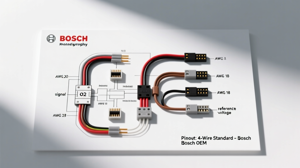
Bosch Universal 4-Wire Narrowband Pinout and Color Codes
The standard Bosch 4-wire narrowband sensor utilizes a zirconium dioxide (ZrO2) sensing element that generates a voltage based on the difference in oxygen content between the exhaust gas and the ambient reference air. The four wires are split into two distinct circuits: the low-impedance signal circuit and the high-current heater circuit.
| Pin / Wire | Standard Bosch Color | Function | Recommended AWG | Destination |
|---|---|---|---|---|
| Signal + | Black | O2 Voltage Signal (0.1V - 0.9V) | 18-20 AWG (Shielded) | ECU O2 Signal Input Pin |
| Signal - | Grey | Dedicated Sensor Signal Ground | 18-20 AWG (Shielded) | ECU Dedicated Sensor Ground Pin |
| Heater + | White (or White/Black) | Heater Element 12V Power | 14-16 AWG | 12V Relay Output (Switched) |
| Heater - | White | Heater Element Ground | 14-16 AWG | Chassis Ground or ECU Heater Ground |
Heater Circuit Design: Relays, Fuses, and AWG Sizing
The most common failure point in custom EFI wiring harnesses is the O2 sensor heater circuit. The internal heater is a Positive Temperature Coefficient (PTC) resistor. Its purpose is to rapidly bring the zirconia element up to its operating temperature of approximately 600°F (315°C) so the ECU can enter closed-loop fuel control immediately after startup.
Understanding Inrush Current and Wire Sizing
When cold, the resistance of a standard Bosch 4-wire heater element is typically between 2.5 and 4.5 ohms at 68°F (20°C). According to Ohm's Law, applying 12V across a 2.5-ohm cold resistance results in an initial inrush current of nearly 4.8 amps. As the element heats up, resistance increases and current drops to a steady state of around 0.8 to 1.2 amps.
Because of this initial surge, wiring the heater circuit directly to a low-amperage ECU driver or using thin gauge wire will result in voltage drop, slow light-off times, or melted harness connectors. For modification projects:
- Wire Gauge: Use a minimum of 14 AWG cross-linked polyethylene (XLPE) or Tefzel wire for both the Heater + and Heater - circuits to eliminate voltage drop over long routing distances in custom chassis.
- Relay Integration: Do not power the heater directly from the ignition switch. Use a standard 30A automotive relay (Bosch-style 5-pin or 4-pin) triggered by an ECU 'Heater Control' output or a switched 12V ignition source.
- Fusing: Install a dedicated 10A mini-ATM fuse on the constant 12V feed side of the relay, located within 18 inches of the power distribution block.
Signal Wire Routing and Dedicated Sensor Grounding
The signal generated by a narrowband O2 sensor is extremely low current (measured in microamps) and highly susceptible to Electromagnetic Interference (EMI) from ignition coils, fuel injectors, and alternator whine. Proper routing and grounding are critical for a stable AFR reading.
The 'Grey Wire' Rule: Never Ground to the Chassis
The single biggest mistake made during garage-built EFI swaps is treating the Grey signal ground wire as a standard chassis ground. The Grey wire must be routed all the way back to the ECU's dedicated analog signal ground pin. Grounding the Grey wire to the engine block or chassis introduces ground offsets (voltage differences between the engine block and the ECU case) directly into the signal wire, causing the ECU to read falsely rich or lean, leading to erratic fuel trims and engine surging.
Shielded Twisted Pair (STP) Implementation
For the Black (Signal) and Grey (Signal Ground) wires, utilize a 2-conductor Shielded Twisted Pair (STP) cable, such as Belden 8760 or equivalent 18 AWG mil-spec shielded wire. The twisting cancels out induced magnetic fields, while the metallic foil shield blocks capacitive coupling from high-voltage ignition wires. Crucial step: The drain wire of the shielded cable must be grounded at the ECU end only. Grounding the shield at both the sensor end and the ECU end creates a ground loop, defeating the purpose of the shield.
Fabricating a Mil-Spec Sensor Harness
In high-vibration and high-heat modification projects (such as track cars or off-road trucks), standard crimp connectors and electrical tape will rapidly fail. Professional harness builders use the following methodology for O2 sensor connections:
- Environmentally Sealed Splices: Use Raychem SolderSleeves (e.g., SO96-xx series) to join the sensor pigtails to your chassis harness. These provide a soldered electrical connection surrounded by hot-melt adhesive heat shrink, creating a completely waterproof seal.
- Conduit Protection: Route the harness through Raychem DR-25 elastomeric heat shrink tubing or braided fiberglass sleeving to protect against exhaust radiant heat and physical abrasion.
- Drip Loops: Always create a physical 'drip loop' in the harness before it enters the sensor boot. This prevents water and condensation from wicking down the wire jacket and into the sensor's reference air vent, which will permanently destroy the zirconia element.
Exhaust Bung Welding Best Practices
Wiring is only half the battle; physical installation dictates sensor lifespan. When welding the 18mm x 1.5mm O2 bung into your custom exhaust:
- Location: Place the bung 18 to 24 inches downstream of the exhaust manifold or turbocharger flange. This allows exhaust gases to mix thoroughly and cools the gas slightly to prevent thermal shock to the sensor.
- Angle: Weld the bung at a 10 to 15-degree upward tilt relative to the ground. This prevents liquid water and condensation from pooling inside the sensor tip during cold starts, a primary cause of premature ceramic element cracking.
Wideband Upgrade Path: Bosch LSU 4.9 vs. Narrowband
While the 4-wire narrowband is excellent for standard stoichiometric closed-loop cruising, forced induction upgrades (turbo/supercharger) or E85 flex-fuel conversions require precise AFR monitoring under wide-open throttle (WOT). In these scenarios, fabricators upgrade to the Bosch LSU 4.9 Wideband O2 Sensor. The LSU 4.9 utilizes a 5-wire harness (incorporating a pump cell and calibration resistor) and requires a dedicated wideband controller (like an AEM X-Series or Innovate Motorsports LC-2) to translate the complex impedance into a 0-5V analog signal that your aftermarket ECU can interpret for 3D fuel map tuning.
Troubleshooting Common O2 Sensor Wiring Faults
When your datalogging software shows erratic AFR readings or the sensor fails to enter closed-loop, use this diagnostic decision tree:
1. Heater Circuit Failure (Sensor stays in open-loop)
- Symptom: ECU datalog shows O2 voltage stuck at 0.0V or 0.45V for minutes after startup.
- Test: Disconnect the sensor. Set a multimeter to Ohms. Measure across the two White wires.
- Specification: Should read between 2.5 and 4.5 ohms at room temperature. If reading 'OL' (Open Loop), the internal heater trace is broken. If reading near 0 ohms, the heater is shorted.
- Fix: Replace sensor. If sensor tests good, check the 10A fuse and verify 12V is reaching the White power wire during cranking.
2. Signal Ground Offset (Erratic fuel trims)
- Symptom: AFR bounces wildly between 12.0 and 16.0 at idle; engine surges.
- Test: With the engine running and ECU connected, backprobe the Black signal wire and the Grey signal ground wire at the ECU connector using a DC voltmeter.
- Specification: Should read a steady 0.45V (stoichiometric) or oscillate smoothly between 0.1V and 0.8V in closed loop.
- Fix: If you see alternator 'whine' (AC voltage ripple) on the multimeter, your shield drain wire is improperly grounded, or the Grey wire is sharing a ground path with high-current devices like fuel injectors. Reroute the Grey wire to a dedicated ECU analog ground pin.
3. False Lean Condition (Exhaust leak)
- Symptom: Sensor reads constant 0.1V (lean), ECU adds excessive fuel, causing rich bog.
- Fix: Inspect the exhaust manifold gaskets and the weld around the O2 bung. Even a microscopic exhaust leak upstream of the sensor will draw in ambient oxygen, tricking the zirconia cell into reporting a lean condition.
References and Technical Standards
For further engineering specifications regarding automotive wiring and sensor integration, consult the following authoritative resources:
- Bosch Motorsport Technical Guide: Oxygen Sensors - Detailed operational parameters and thermal limits for Bosch Zirconia and LSU sensors.
- SAE J1128: Low Tension Primary Cable Standard - Society of Automotive Engineers specifications for wire insulation, temperature ratings, and AWG sizing in engine bays.
- Holley EFI Wiring Manual (Part #10555) - Comprehensive aftermarket ECU pinout guidelines, dedicated sensor grounding protocols, and relay integration schematics.