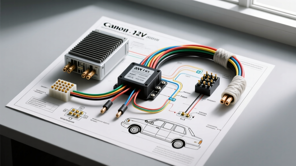
Technical Specification Reference: Mobile 12V DC Evaporative Cooling Systems
Mobile evaporative coolers (often referred to as swamp coolers) are highly efficient climate control solutions for Class 8 sleeper cabs, overland expedition vehicles, and off-grid RV conversions. Unlike traditional compressor-based RV air conditioners that require 120V AC shore power or massive inverter setups, 12V DC evaporative coolers leverage the ambient dry-bulb and wet-bulb temperature differential to cool the cabin. However, integrating these systems into a vehicle's auxiliary electrical system requires precise circuit management. When engineering the auxiliary power distribution for an overland rig or commercial truck, referencing an accurate wiring diagram for evaporative cooler systems is critical to prevent voltage sag, PWM signal interference, and premature water pump failure.
This technical reference outlines the exact wire gauges, relay pinouts, PWM control logic, and bulkhead connector specifications required for a reliable 12V DC evaporative cooler installation, adhering to SAE J1128 Low Tension Primary Cable standards and RV Industry Association (RVIA) electrical guidelines.
Core Electrical Architecture & Load Calculations
A standard mobile evaporative cooler consists of three primary electrical loads: the centrifugal blower motor, the submersible water circulation pump, and the electronic control module (often featuring PWM speed control and low-water cutoff logic). Because these units are typically mounted on the roof or exterior bulkhead of a vehicle, wire run lengths frequently exceed 15 feet, making voltage drop calculations mandatory.
According to Blue Sea Systems DC wiring guidelines, a maximum voltage drop of 3% is recommended for critical auxiliary loads. For a 12V nominal system, this means the voltage at the cooler's terminal block must not fall below 11.64V under maximum load. Using undersized wire will cause the PWM controller to reset, the blower motor to overheat, and the water pump to lose prime.
Component Amperage & AWG Wire Sizing Chart
The following specifications are based on a standard 250W mobile evaporative cooler unit operating on a 12V DC nominal system with a 20-foot round-trip wire run.
| Component | Max Draw (A) | Recommended AWG | Wire Type (SAE J1128) | Inline Fuse | Connector Type |
|---|---|---|---|---|---|
| Centrifugal Blower Motor | 18.5A | 10 AWG | TXL or GXL | 25A ATO | Deutsch DT 2-Pin |
| Submersible Water Pump | 3.2A | 16 AWG | TXL | 5A Mini | Weather-Pack 2-Pin |
| PWM Control Signal | 0.05A | 18 AWG | GXL Shielded | N/A (Fused via ECU) | Deutsch DT 4-Pin |
| Low-Water Float Switch | 0.5A | 18 AWG | TXL | 2A Micro2 | Spade / Heat Shrink |
Step-by-Step Wiring Diagram for Evaporative Cooler Integration
Proper integration requires separating the high-amperage blower circuit from the sensitive PWM signal and low-amperage water pump circuits. Combining these on a single unshielded harness will result in electromagnetic interference (EMI), causing the blower speed to fluctuate erratically.
1. Blower Motor & PWM Speed Control Circuit
Modern 12V DC evaporative coolers utilize 4-pin PWM (Pulse Width Modulation) brushless blowers. This allows the cabin thermostat to modulate fan speed smoothly rather than cycling the motor on and off, which draws massive inrush currents.
- Pin 1 (VCC / 12V+): Red wire, 10 AWG TXL. Connects directly to the auxiliary fuse block via a 30A Bosch-style ISO relay (Pin 87). Must handle the continuous 18.5A draw plus a 20% safety margin.
- Pin 2 (GND): Black wire, 10 AWG TXL. Routes to a dedicated chassis ground stud. Do not ground this to the thin sheet metal of the RV roof; route it to the main structural frame or a reinforced ground bus bar.
- Pin 3 (PWM Signal): Blue wire, 18 AWG Shielded. Carries the 20kHz square wave signal from the interior cabin controller. The shield drain wire must be grounded at the controller end only to prevent ground loops.
- Pin 4 (Tachometer / RPM Feedback): Yellow wire, 18 AWG. Sends a pulse back to the controller to verify motor operation. If the controller detects 0 RPM while the PWM signal is active, it triggers a fault code and cuts power to prevent a locked-rotor fire hazard.
2. Water Pump & Low-Level Cutoff Sensor Wiring
The water circulation pump wicks water over the cooling media pads. Running the pump dry will destroy the impeller and motor windings within minutes. The wiring diagram for the evaporative cooler must include a hardware-level low-water cutoff circuit that physically interrupts the pump's ground path.
The submersible pump's positive lead (16 AWG, Red) connects to a switched 12V source on the auxiliary fuse panel. The negative lead (16 AWG, Black) routes through a normally-closed (NC) magnetic float switch located in the cooler's sump reservoir. When the water level drops below the safe threshold, the float drops, the NC switch opens, and the pump's ground circuit is broken instantly. This hardware interrupt is fail-safe and operates independently of the main PWM logic board.
Relay Pinout & Auxiliary Fuse Block Configuration
To protect the vehicle's primary starting battery and alternator, the evaporative cooler must be wired to a secondary auxiliary battery bank (e.g., Lithium LiFePO4 house batteries) via a DC-to-DC charger or a heavy-duty continuous duty solenoid. The main power feed to the cooler's relay bank should utilize 4 AWG battery cable, stepped down at a marine-grade terminal block.
Standard Bosch ISO 7588 Mini Relay Pinout (Main Blower Power)
| Relay Pin | Function | Wire Size & Color | Destination |
|---|---|---|---|
| 30 | Constant 12V+ Input | 8 AWG Red | Auxiliary Fuse Block (40A Mega Fuse) |
| 85 | Relay Coil Ground | 16 AWG Black | Chassis Ground Bus |
| 86 | Relay Coil Trigger (+) | 16 AWG Blue | Cabin Master HVAC Switch |
| 87 | Switched 12V+ Output | 10 AWG Red | Blower Motor Pin 1 (VCC) |
Note: Always install a flyback diode (1N4007) across pins 85 and 86 (cathode to 86, anode to 85) to suppress the inductive voltage spike generated when the relay coil de-energizes. This spike can otherwise destroy the sensitive PWM microcontroller on the evaporative cooler's main board.
Bulkhead Routing and IP67 Waterproofing
Passing wiring from the exterior roof-mounted evaporative cooler into the climate-controlled cabin requires strict adherence to IP67 waterproofing standards. Standard rubber grommets are insufficient for high-speed highway driving or heavy off-road rain exposure.
- Connector Selection: Terminate all exterior wires into a Deutsch DT04-4P receptacle mounted on the interior side of the bulkhead. The exterior cooler harness should terminate in a DT06-4S plug with integrated silicone wedge locks and secondary O-ring seals.
- Crimp Tooling: Use a precision DT crimp tool (e.g., HDP20 series) to ensure the wire barrel and insulation barrel are uniformly compressed. A poor crimp will wick moisture via capillary action directly into the PWM controller.
- Drip Loops: Before the harness enters the bulkhead connector, create a physical 'drip loop' where the cable dips below the entry hole. This ensures that water running down the exterior cable jacket drips off the bottom of the loop rather than pooling against the Deutsch connector seal.
Troubleshooting Common 12V Evaporative Cooler Faults
When diagnosing electrical faults in mobile swamp coolers, technicians must differentiate between mechanical failures (calcified media pads, seized pump impellers) and electrical anomalies. Use the following decision tree for rapid troubleshooting:
Symptom: Blower Motor Stutters or Shuts Down at High RPM
- Cause: Voltage drop exceeding 3% on the 12V+ feed wire. As PWM duty cycle approaches 100%, amperage peaks. If the wire gauge is too small, voltage at the motor drops below the controller's low-voltage lockout (LVLO) threshold, typically 10.5V.
- Fix: Measure voltage directly at the blower's Pin 1 while under load. If below 11.6V, upgrade the feed wire from 12 AWG to 10 AWG TXL, and verify the chassis ground connection is free of paint and corrosion.
Symptom: Water Pump Runs Continuously Even When Unit is 'Off'
- Cause: The main ISO relay (Pin 87) has suffered contact welding due to repeated inrush current arcing from the pump's inductive load, or the cabin switch is shorting to 12V+.
- Fix: Pull the inline 5A Mini fuse for the pump circuit. If the pump stops, the fault lies upstream in the switch or logic board. If the pump continues to run, the relay contacts are fused; replace the relay and install a snubber diode across the pump terminals to absorb inductive kickback.
Symptom: Erratic Fan Speeds and Cabin Controller Reboots
- Cause: Electromagnetic Interference (EMI) from the unshielded PWM signal wire running parallel to the high-amperage blower power wires.
- Fix: Reroute the 18 AWG PWM signal wire at least 6 inches away from the 10 AWG power cables. Replace standard wire with SAE J1128 compliant shielded cable, ensuring the drain wire is properly terminated to the ground bus.
Conclusion
Engineering a robust 12V DC electrical architecture for mobile climate control requires strict adherence to wire sizing, relay logic, and environmental sealing protocols. By following this wiring diagram for evaporative cooler systems, automotive electricians and RV builders can ensure reliable, efficient operation in the harshest off-grid environments, maximizing battery life and preventing catastrophic thermal failures.