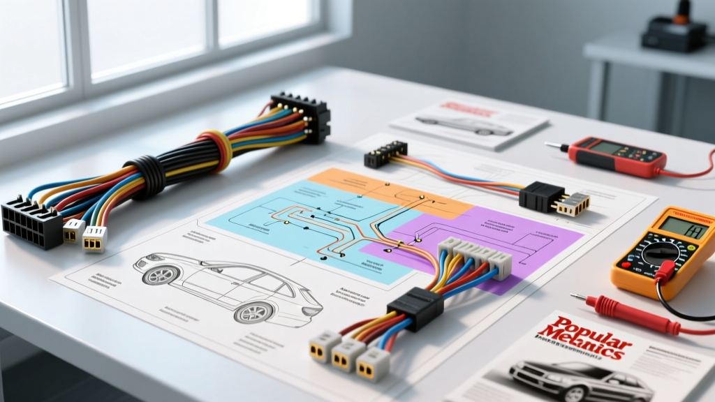
The True Cost of Automotive Electrical Diagnostics
Many DIYers and novice technicians search for guides on how to read car wiring diagrams, assuming that simply understanding the symbols is enough to fix a vehicle. However, interpreting a schematic is only 20% of the diagnostic battle. The remaining 80% relies on possessing the correct diagnostic tools to verify the visual data against real-world electrical values. A wiring diagram tells you that a 5-volt reference signal travels from the Powertrain Control Module (PCM) to a Manifold Absolute Pressure (MAP) sensor via a 20 AWG wire, but it will not tell you if that wire has a micro-fracture causing a voltage drop under engine vibration.
This cost and tool requirements analysis breaks down exactly what you need to budget for to accurately trace, test, and verify the circuits depicted in OEM wiring schematics. From sourcing the correct manuals to investing in high-impedance multimeters and breakout boxes, understanding the financial and technical barriers to entry is crucial for any serious automotive electrician.
Sourcing the Schematics: OEM vs. Aftermarket Costs
Before you can trace a circuit, you need the schematic. The cost of acquiring accurate wiring diagrams varies wildly depending on whether you choose OEM (Original Equipment Manufacturer) publications or aftermarket aggregator software. OEM diagrams, such as those sourced from Helm Incorporated, use manufacturer-specific symbols and exact factory splice pack locations. Aftermarket solutions standardize these symbols to ISO formats, which can sometimes obscure factory-specific grounding strategies.
| Source Type | Provider Example | Estimated Annual Cost | Symbol Standard | Best Use Case |
|---|---|---|---|---|
| OEM Service Manuals | Helm Inc. / Factory Service | $150 - $300 (Per Vehicle) | Manufacturer Specific | Deep ECU pinout tracing, harness routing |
| Aftermarket Pro | AllData Professional | $250+ (Per Vehicle/Year) | Standardized ISO | Multi-vehicle shop environments |
| Aftermarket DIY | AllData DIY / eManualOnline | $29.95 - $50.00 (One-time) | Standardized ISO | Basic sensor testing, component location |
The Diagnostic Toolkit: Pricing and Application
Knowing how to read car wiring diagrams is useless if your testing equipment alters the circuit's behavior or damages the harness. Modern vehicles utilize Controller Area Network (CAN) bus systems and sensitive 5V logic boards that require specialized, high-impedance testing tools.
Digital Multimeters (DMM) and Impedance Testing
To properly test the nodes identified in a wiring diagram, you must use a DMM with an input impedance of at least 10 Megohms. Using a cheap, low-impedance test light or analog meter on a 5V reference circuit will draw excessive current, potentially frying the PCM's internal voltage regulator. The industry standard is the Fluke 88V Automotive Multimeter, which retails for approximately $450 to $500. It features specialized automotive modes for RPM, dwell, and min/max recording, which are essential for capturing intermittent voltage drops while the vehicle is in motion. For budget-conscious diagnosticians, the Power Probe IV (approx. $250) offers excellent circuit tracing capabilities, though it must be used with extreme caution around SRS (airbag) and CAN-bus circuits to avoid deploying modules or shorting data lines.
Back-Pinning Probes vs. Wire Piercing
A common, destructive mistake made by novices is using wire-piercing probes to test circuits shown in the diagram. Piercing the insulation of an 18 AWG or 20 AWG CAN-bus wire introduces moisture, leading to copper oxidation and eventual high-resistance failures. The correct, cost-effective method is back-pinning the connector.
Investing in a high-quality back-pin probe set ($40 to $80) is mandatory. These ultra-thin stainless steel probes are designed to slip past the silicone weather seals of common automotive connectors, such as the Delphi Metri-Pack 150 (1.5mm blade) and TE Connectivity GT280 series, allowing you to make contact with the terminal without damaging the wire insulation or expanding the female terminal housing.
Applied Schematic Reading: Tracing a CAN-Bus Fault
Let us apply the concept of reading a diagram alongside tool requirements to a real-world scenario. Consider a diagnostic trouble code U0100 (Lost Communication with ECM) on a late-model GM or Ford platform. The wiring diagram will direct you to the Data Link Connector (DLC), specifically the J1962 standard 16-pin OBD-II port.
- Pin 6: CAN-High (Typically White/Blue or Dark Green)
- Pin 14: CAN-Low (Typically White or Dark Blue)
- Pin 4 & 5: Chassis and Signal Grounds
According to SAE International standards, the CAN-High line should idle around 2.5V and spike to 3.5V, while CAN-Low idles at 2.5V and drops to 1.5V. To test this without shorting Pin 6 to Pin 7 (which is often K-Line or J1850), you cannot simply jam multimeter probes into the DLC. You must invest in an OBD-II Breakout Box ($45 to $90). This tool plugs into the DLC and provides safe, isolated test points for every pin, allowing you to verify the differential voltage exactly as the wiring diagram dictates. Furthermore, checking the terminating resistors requires the ignition to be OFF; the diagram will show two 120-ohm resistors in parallel across the CAN-H and CAN-L lines, meaning your DMM should read exactly 60 ohms when back-pinning the DLC.
When Diagrams Demand Advanced Tooling: Oscilloscopes
There is a ceiling to what a DMM can achieve, even when you know exactly how to read car wiring diagrams. If you are diagnosing a Pulse Width Modulated (PWM) cooling fan circuit, a variable valve timing (VVT) solenoid, or a corrupted CAN-bus waveform suffering from electromagnetic interference (EMI), a multimeter's refresh rate is too slow. The diagram will show you the ground switching path, but only an oscilloscope will show you the inductive voltage spike (kickback) when the ground is removed.
Entry-level automotive oscilloscopes, such as the PicoScope 4225A or comparable Hantek models, range from $400 to $1,500+. While this is a steep initial investment, it eliminates the 'parts cannon' approach of replacing ECUs and sensors based on guesswork, ultimately saving money on complex electrical faults.
Summary Cost Matrix: Building Your Diagnostic Arsenal
Below is a structured budget matrix for building a toolkit capable of fully leveraging OEM wiring schematics, ranging from essential DIY setups to professional-grade electrical bays.
| Equipment Category | Essential DIY Budget | Professional Shop Budget | Primary Schematic Application |
|---|---|---|---|
| Diagram Software | $30 (eManualOnline) | $300+ (AllData/Helm OEM) | Locating splice packs, ground points, and pinouts |
| Digital Multimeter | $60 (Innova 3340) | $450 (Fluke 88V) | Testing 5V refs, continuity, and 60-ohm CAN terminations |
| Connector Probing | $15 (Basic Paperclips) | $80 (Delphi/TE Back-pin Kit) | Safe testing of Metri-Pack 150/280 without seal damage |
| DLC Breakout Box | $45 (Generic 16-Pin) | $120 (OEM-Trained Box) | Isolating DLC Pin 6/14 for network topology testing |
| Oscilloscope | N/A (Skip for basics) | $1,200+ (PicoScope 4-Ch) | Verifying PWM signals, injector waveforms, and EMI noise |
| Total Estimated Cost | ~$150 | ~$2,150+ | Capability scales with investment |
Ultimately, learning how to read car wiring diagrams is an exercise in logic and preparation. The schematic is your map, but your tools are the vehicle that gets you to the destination. By investing in high-impedance testing equipment, proper back-pinning probes, and accurate OEM documentation, you transition from simply guessing at electrical faults to definitively proving circuit integrity based on hard engineering data.