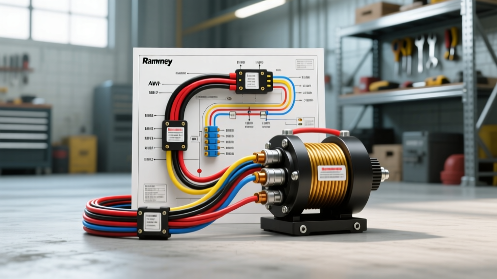
Introduction to Ramsey Winch Electrical Architecture
Installing a heavy-duty 12V DC winch requires more than just bolting hardware to a bumper. The electrical system is the lifeline of your recovery gear, and a flawed installation can lead to catastrophic voltage drop, melted insulation, or total contactor failure under peak load. Whether you are rigging a Ramsey REP 8000, a Patriot 9500, or a Ranger series, understanding the exact wiring diagram for Ramsey winch configurations is critical for safe, reliable operation.
This practical how-to installation guide provides professional-grade wiring schematics, specific AWG cable requirements, solenoid pinout mappings, and real-world troubleshooting protocols. We treat the winch not just as a mechanical accessory, but as a massive electrical load that demands dedicated, high-amperage circuit management.
Safety Protocols and Preparation
Before touching a single cable, disconnect the negative terminal of your vehicle's main battery. Winch circuits routinely carry 300 to 450 amps under stall load. A short circuit without a primary breaker can instantly weld tools to battery terminals and ignite harness insulation. Ensure your work area is dry, and utilize insulated hand tools rated for at least 1000V.
Electrical Specifications and Component Sizing
The most common failure point in aftermarket winch installations is undersized cabling. Factory-included winch leads are often too short and gauge-starved for vehicles with relocated batteries or extended front bumpers. Refer to the chart below to select the correct wire gauge based on your Ramsey winch's maximum pull rating and the total round-trip cable length.
| Winch Rated Pull (lbs) | Max Amp Draw (Stall) | Cable Length (Round Trip) | Minimum AWG Size | Primary Circuit Breaker |
|---|---|---|---|---|
| 8,000 - 9,500 | 350A - 400A | Up to 20 ft | 2 AWG | 175 Amp DC Resettable |
| 8,000 - 9,500 | 350A - 400A | 20 ft to 40 ft | 1/0 AWG | 225 Amp DC Resettable |
| 10,000 - 12,000 | 400A - 450A | Up to 20 ft | 1/0 AWG | 225 Amp DC Resettable |
| 10,000 - 12,000 | 400A - 450A | 20 ft to 50 ft | 2/0 AWG | 250 Amp DC Resettable |
For circuit protection, always utilize a marine-grade, ignition-protected DC circuit breaker. Standard automotive fuses cannot handle the inrush current of a winch motor. For comprehensive wire sizing charts and voltage drop calculations, refer to the Blue Sea Systems Wire Sizing Guide, which aligns with SAE and ABYC standards for high-draw DC accessories.
Step-by-Step Contactor and Cable Installation
Most modern Ramsey winches utilize a 4-terminal heavy-duty solenoid (contactor) rather than a traditional 3-post setup. This isolates the high-amperage motor current from the low-amperage remote switch circuit, drastically reducing voltage drop to the coil.
Step 1: Mount the Contactor and Circuit Breaker
Mount the solenoid pack and the primary circuit breaker in a protected, dry zone within the engine bay. The breaker must be installed on the positive main feed within 18 inches of the battery positive terminal. If routing through the firewall or grille, use heavy-duty grommets to prevent chassis grounding.
Step 2: Route the Main Power Feed
Run your primary positive cable (Red, 1/0 AWG) from the battery positive terminal to the input side of the circuit breaker. From the output side of the breaker, run a second 1/0 AWG cable to the large 'BATT' stud on the winch contactor. Pro-Tip: Use adhesive-lined marine heat shrink on all crimped lugs. Standard PVC heat shrink allows moisture ingress, leading to green copper corrosion and increased resistance over time.
Step 3: Connect the Motor Leads
Connect the heavy-gauge motor leads from the contactor's 'MOTOR' stud directly to the winch motor terminal. The motor ground cable must be routed directly back to the vehicle's chassis ground bus or the negative battery terminal. Never rely solely on the winch mounting bolts for the primary ground path; vibration and paint will cause severe resistance.
Step 4: Torque Specifications
Proper torque is critical. Under-torqued lugs create micro-arcing and heat; over-torqued lugs strip the soft brass threads of the contactor studs. For standard 3/8'-16 solenoid studs, apply 15 to 18 ft-lbs of torque. Apply a thin layer of dielectric grease over the assembled terminal to block oxidation.
Wiring Diagram for Ramsey Winch: Remote Receptacle
The remote control socket allows you to operate the winch from a safe distance. Depending on your specific Ramsey model, you will encounter either a 3-pin or 4-pin aircraft-style receptacle. Below is the standard pinout mapping for the low-amperage control circuit.
| Pin / Terminal | Wire Color (Typical) | Function | Destination |
|---|---|---|---|
| Pin 1 (Common) | Red (12 AWG) | Switched 12V Power | Ignition Source or Contactor Small Stud (+) |
| Pin 2 (In) | Yellow (12 AWG) | Spool In Signal | Contactor Small Stud (IN Coil) |
| Pin 3 (Out) | Green (12 AWG) | Spool Out Signal | Contactor Small Stud (OUT Coil) |
| Pin 4 (Ground) | Black (12 AWG) | Control Circuit Ground | Clean Chassis Ground |
When wiring the remote socket, ensure the dust cap is tethered. Moisture inside the 12-pin or 4-pin connector will cause the winch to 'ghost' or activate spontaneously due to electrolytic bridging between the pins.
Advanced Troubleshooting and Voltage Drop Testing
Even with a perfect wiring diagram for Ramsey winch setups, real-world conditions can introduce faults. If your winch clicks but won't turn, or turns sluggishly, do not immediately condemn the motor. Perform a voltage drop test.
The Voltage Drop Protocol
A voltage drop test measures the energy lost as heat across connections and cables while the circuit is under load. You will need a digital multimeter (DMM) and a heavy load (such as wrapping the winch line around a sturdy tree with a snatch block to create resistance).
- Set DMM to DC Volts: Place the red probe on the battery positive post and the black probe on the winch motor positive terminal.
- Apply Load: Engage the winch 'IN' command. The motor should strain against the load.
- Read the Drop: The multimeter displays the voltage lost in the positive circuit. According to SAE standards, a drop greater than 0.50V on the positive side indicates high resistance (bad crimp, corroded breaker, or undersized wire).
- Test the Ground: Move the red probe to the motor casing (clean metal) and the black probe to the battery negative post. The acceptable ground drop is 0.20V or less.
Common Failure Modes
- Rapid Clicking Solenoid: This indicates the control coil is receiving insufficient voltage to hold the heavy contacts closed. Check the 12 AWG remote wiring for corrosion, or test the vehicle's alternator output. If the battery drops below 10.5V under load, the coil will chatter.
- Melted Contactor Boots: Caused by loose lug nuts on the main studs. The resulting micro-arcing generates extreme localized heat, melting the rubber insulators before tripping the primary breaker.
- Motor Overheating without Stall: Often caused by internal brush wear or a shorted armature winding, but can also be triggered by chronic low-voltage operation due to undersized AWG cables spanning long distances.
Maintenance and Final Inspection
After completing the installation and verifying the polarity with a quick 'bump' of the remote, secure all cabling with UV-resistant split loom and heavy-duty zip ties. Keep high-amperage winch cables away from exhaust manifolds and steering shafts. For official torque specs, exploded views, and OEM replacement part numbers, always consult the Ramsey Winch Official Manuals Archive.
By adhering strictly to these AWG requirements, utilizing marine-grade heat shrink, and validating your work with a voltage drop test, your Ramsey winch will deliver maximum line-pull reliability when you need it most in the backcountry.