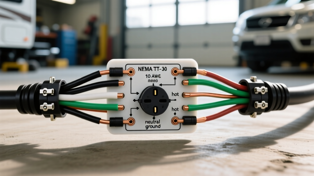
The Anatomy of a 30-Amp RV Electrical System
When wiring a recreational vehicle pedestal, installing a dedicated home camper circuit, or replacing a damaged shore power cord, understanding the exact wiring diagram 30 amp RV plug configuration is critical for safety and equipment preservation. Unlike standard household outlets or heavy-duty dryer receptacles, the 30-amp RV plug operates on a unique standard known as NEMA TT-30. This configuration delivers 125V AC at a maximum of 30 amps, utilizing a three-prong, three-wire grounding system.
A common and catastrophic mistake made by novice DIYers is confusing the NEMA TT-30 (120V) with the NEMA 10-30 or 14-30 (240V) dryer receptacles. Plugging an RV into an improperly adapted 240V source will instantly destroy the vehicle's onboard power converter, inverters, and roof-mounted air conditioning units. This guide provides the definitive wiring schematic, pinout specifications, and a rigorous product comparison of the top NEMA TT-30R receptacles and wiring materials on the market, ensuring your installation meets the National Electrical Code (NFPA 70) Article 551 standards for recreational vehicle parks.
Wiring Diagram 30 Amp RV Plug: Pinout and Color Codes
The NEMA TT-30P (Plug) and TT-30R (Receptacle) feature three distinct blades/pins arranged in a specific geometry to prevent cross-mating with 240V devices. The hot blade is straight, the neutral blade is L-shaped (or U-shaped depending on the manufacturer's casting), and the ground pin is a standard U-shape. Below is the definitive wiring mapping for both the male plug and female receptacle.
Table 1: NEMA TT-30 Pin Assignments and Wire Color Codes
| Terminal Designation | Function | OEM Wire Color | Screw Terminal Color | Blade / Pin Shape |
|---|---|---|---|---|
| X (or Hot) | 125V AC Line | Black | Brass / Gold | Straight Blade |
| W (or Neutral) | Return Path | White | Silver / Nickel | L-Shaped / Hooked |
| G (or Ground) | Equipment Ground | Green (or Bare) | Green | U-Shaped Pin |
Expert Note: When wiring the male plug (TT-30P) onto a replacement shore power cord, always route the Black (Hot) wire to the Brass terminal, White (Neutral) to the Silver terminal, and Green (Ground) to the Green terminal. Ensure the cord grip clamp secures the outer jacket of the cable, not the individual insulated conductors, to prevent tension from pulling the wires out of the terminal blocks.
Product Comparison: Top NEMA TT-30R Receptacles
Selecting the correct receptacle for your RV pedestal or garage outlet is just as important as the wiring itself. Receptacles are subjected to high continuous loads (often running near 24-28 amps for hours when the AC compressor is engaged), outdoor UV exposure, and extreme temperature fluctuations. We compared three industry-standard NEMA TT-30R receptacles to help you choose the best component for your installation.
Leviton vs. Hubbell vs. Bryant TT-30R Receptacles
1. Hubbell 9430R (Heavy-Duty Thermoset): Hubbell is the gold standard for industrial and heavy-duty RV park wiring. The 9430R utilizes a thermoset housing, which offers superior resistance to high heat, arcing, and UV degradation compared to standard thermoplastics. The terminal screws feature deep-thread clamping plates that grip 10 AWG stranded wire securely without fraying the copper strands. According to the Hubbell Wiring Device-Kellems TT-30R specifications, this unit is rated for continuous 30A loads at 125V.
2. Leviton 306-000 (Residential Thermoplastic): Leviton's offering is the most common receptacle found in big-box hardware stores. It features a high-impact thermoplastic face and a steel mounting strap. While adequate for occasional weekend camper use, the thermoplastic material can become brittle under prolonged UV exposure and extreme cold. The side-wire terminal screws are standard brass and require careful torqueing to avoid stripping.
3. Bryant 9430FR (Flush Receptacle, Nylon): Bryant (now part of Hubbell) offers a rugged nylon housing that provides excellent impact resistance. The flush-mount design sits tighter against the weatherproof cover, reducing moisture ingress. The internal contacts are made from high-conductivity brass, minimizing voltage drop across the receptacle itself.
Table 2: TT-30R Receptacle Comparison Chart
| Feature | Hubbell 9430R | Leviton 306-000 | Bryant 9430FR |
|---|---|---|---|
| Housing Material | Thermoset (High Heat) | Thermoplastic | Nylon (High Impact) |
| Terminal Type | Back/Side Wire Clamp | Side Wire Screw | Side Wire Screw |
| Max Wire Capacity | #8 AWG | #10 AWG | #10 AWG |
| UV Resistance | Excellent | Fair | Good |
| Best Application | RV Parks / Daily Use | Home Garage / Occasional | Outdoor Pedestals |
Wire Gauge Selection and Voltage Drop Calculations
The RV Industry Association (RVIA) technical standards and the NEC mandate a minimum of 10 AWG copper wire for 30-amp circuits. However, wire gauge selection must also account for voltage drop, especially in long runs from the main service panel to the RV pedestal. A voltage drop exceeding 3% at the farthest outlet can cause RV air conditioner compressors to overheat, draw excessive amperage, and trip the main pedestal breaker.
Table 3: Voltage Drop for 10 AWG vs. 8 AWG Copper at 30 Amps (120V)
| One-Way Run Distance | 10 AWG Copper Drop | 8 AWG Copper Drop | Recommendation |
|---|---|---|---|
| 50 Feet | 2.1% (2.5V) | 1.3% (1.6V) | 10 AWG Acceptable |
| 100 Feet | 4.2% (5.0V) | 2.6% (3.1V) | Upgrade to 8 AWG |
| 150 Feet | 6.3% (7.5V) | 3.9% (4.7V) | Mandatory 8 AWG |
Insulation Type Selection: For runs inside PVC conduit, use THHN/THWN-2 stranded copper. Stranded wire is significantly easier to pull through conduit bends and offers better vibration resistance at the terminal screws. For direct burial applications without conduit, you must use 10/3 or 8/3 UF-B (Underground Feeder) cable, ensuring the outer PVC jacket is rated for moisture and soil acidity.
Step-by-Step Installation & Torque Specifications
Proper termination is where most 30-amp RV circuits fail. Loose connections create high resistance, generating immense heat that melts the receptacle face and causes arcing.
- Strip the Jacket: Remove exactly 2.5 inches of the outer cable jacket to expose the three conductors.
- Strip the Conductors: Strip 5/8 inch of insulation from the Black, White, and Green wires. Do not nick the copper strands; a nicked wire creates a localized hot spot.
- Form the Hook: If using solid wire, bend the exposed copper into a tight 'J' hook using needle-nose pliers. If using stranded wire, twist the strands tightly or crimp a 10 AWG fork terminal.
- Terminal Orientation: Loop the wire hook clockwise around the terminal screw. This ensures that tightening the screw pulls the wire loop tighter rather than pushing it out.
- Apply Torque: Tighten the terminal screws to 14-18 in-lbs. Use a calibrated torque screwdriver. Overtightening will strip the brass threads; undertightening will cause a fire hazard.
- Secure the Cord Grip: For male plug replacements, ensure the internal strain relief clamp bites down firmly on the thick outer jacket of the shore power cord.
Troubleshooting Common TT-30 Wiring Faults
Before plugging your RV into a newly wired 30-amp receptacle, always verify the wiring with a digital multimeter and a standard 3-prong receptacle tester. Here are the most common failure modes and how to identify them:
- Reverse Polarity (Hot/Neutral Swapped): If the Black and White wires are reversed at the receptacle, the RV's internal breakers will still function, but the chassis of the RV may become energized if there is an internal appliance fault. A receptacle tester will show a 'Red/Yellow' light pattern. Fix: Swap the wires on the Brass and Silver terminals.
- Open Ground: The Green wire is disconnected or broken. This defeats the safety path for fault currents. Fix: Verify continuity from the receptacle ground terminal back to the main panel ground bus bar.
- High Resistance Joint (Voltage Drop under Load): The receptacle reads 122V with no load, but drops to 105V when the RV AC kicks on. This indicates a loose terminal screw or a damaged wire strand at the connection point. Fix: Turn off the breaker, open the receptacle, and re-torque all terminal connections to 18 in-lbs.
- The 240V Fatal Flaw: If you measure 240V between the Hot (X) and Neutral (W) terminals, the circuit has been wired to a 2-pole 240V breaker instead of a 1-pole 120V breaker. Do not plug in the RV. Fix: Move the hot wire to a single-pole 30A breaker connected to one phase leg, and ensure the neutral is landed exclusively on the neutral bus bar.
Final Selection Verdict
For a permanent, outdoor RV pedestal that will see daily use and harsh weather, the Hubbell 9430R paired with 8 AWG THWN-2 stranded copper (for runs over 50 feet) is the undisputed best choice. The thermoset housing prevents the melting issues common with cheaper thermoplastic alternatives, and the heavy-duty clamping plates ensure a maintenance-free, low-resistance connection that will safely power your camper's electrical systems for decades.