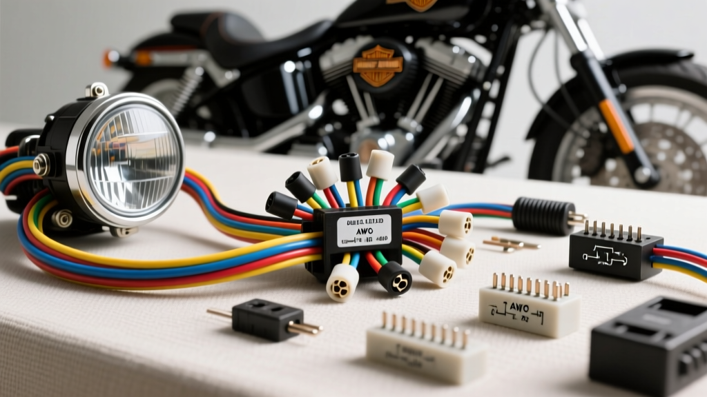
Decoding the Harley Headlight Wiring Diagram
Whether you are restoring a classic 1998 Dyna Super Glide or upgrading the front lighting on a 2021 Road Glide, understanding the underlying electrical architecture is critical. A Harley headlight wiring diagram is not just a map of wires; it is a blueprint for managing current draw, preventing voltage drop, and communicating with the motorcycle's Body Control Module (BCM). When planning a lighting repair or an LED conversion, analyzing the cost and tool requirements upfront prevents blown fuses, melted connectors, and dreaded dashboard flash codes.
Harley-Davidson has utilized two primary headlight connector standards over the last three decades: the traditional 3-prong H4 ceramic pigtail (common on older carbureted and early Twin Cam models) and the modern 7-pin or 9-pin sealed Molex connectors (standard on 2014+ Touring and newer Softail platforms). According to SAE J1123 standards for motorcycle headlamps, proper circuit integrity requires specific wire gauges and terminal crimp profiles to handle the thermal load of halogen bulbs or the CAN-BUS signaling of modern LEDs.
Standard H4 vs. 7-Pin Molex Pinouts
Before purchasing components, you must identify your connector type. The H4 system relies on a simple switched-ground or switched-power setup, while the 7-pin Molex integrates running lights, turn signals, and BCM data lines into a single sealed housing.
| Connector Type | Pin / Prong | Wire Color (OEM) | Function | Required AWG |
|---|---|---|---|---|
| H4 (3-Prong) | Pin 1 | Black | Ground | 14 AWG |
| H4 (3-Prong) | Pin 2 | Yellow | Low Beam (+12V) | 14 AWG |
| H4 (3-Prong) | Pin 3 | Blue | High Beam (+12V) | 14 AWG |
| 7-Pin Molex | Pin 1 | Yellow/Black | Low Beam Power | 14 AWG |
| 7-Pin Molex | Pin 2 | Blue/White | High Beam Power | 14 AWG |
| 7-Pin Molex | Pin 3 | Black | Main Ground | 14 AWG |
| 7-Pin Molex | Pin 4 | Red/White | Running Light / Halo | 18 AWG |
Essential Tool Requirements for the Job
Attempting to wire a Harley headlight using generic automotive tools is a primary cause of connector failure. The vibration inherent to V-Twin engines demands aerospace-grade crimps and high-temperature materials. Below is the mandatory tooling checklist for a professional-grade installation.
- Molex MX150 Terminal Crimper: If your bike uses a 7-pin sealed connector, you must use a crimp tool specifically calibrated for Molex MX150 terminals (such as the Molex 63811-1000). Standard open-barrel crimpers will deform the terminal, causing it to hang up in the connector housing and fail the pin-pull test. Reference the Molex MX150 Connector Specifications for exact die cavity settings.
- Titanium-Coated Wire Strippers (14-18 AWG): Harley-Davidson uses TXL (Cross-linked polyethylene) or GXL high-temperature wire. TXL insulation is thinner but significantly harder than standard PVC. Precision strippers prevent nicking the copper strands, which reduces the wire's ampacity and creates a hot spot.
- Digital Multimeter (DMM) with Min/Max Hold: Essential for testing voltage drop. You need a meter capable of reading millivolt drops across the ground circuit while the high beam is engaged.
- Adhesive-Lined Marine Heat Shrink: Standard electrical tape will unravel due to engine heat and UV exposure. Use 3M or equivalent dual-wall heat shrink with an inner meltable adhesive layer to seal out moisture and prevent green corrosion at the terminal crimps.
- Terminal Extraction Tool Set: Essential for removing pinned wires from the 7-pin Molex or Deutsch DT housings without breaking the secondary locking tangs.
Cost Analysis: Repair vs. LED Upgrade Paths
Understanding the financial commitment of your wiring project helps in sourcing the right components. Upgrading from a 55W halogen to a 20W LED projector alters the electrical load, which dictates whether you need to spend extra on CAN-BUS decoders or heavy-duty relays.
| Upgrade Path | Component Cost | Wiring/Tool Cost | Total Estimated Cost | Complexity |
|---|---|---|---|---|
| OEM Halogen Bulb Replacement | $15 - $25 | $0 (Reuse pigtail) | $15 - $25 | Low |
| H4 Ceramic Pigtail Repair | $12 (Pigtail & Solder) | $35 (Heat shrink, crimpers) | $47 | Medium |
| LED Drop-In Bulb (H4 Base) | $40 - $80 | $25 (CAN-BUS Decoder) | $65 - $105 | Medium |
| Full 7-Inch LED Projector Housing | $150 - $350 | $45 (Molex pigtail, tools) | $195 - $395 | High |
Note: If you are installing an LED drop-in bulb on a 2014 or newer Harley with a BCM, you must factor in the cost of an inline CAN-BUS decoder ($20-$30). Without it, the BCM will detect the low current draw of the LED and trigger a dashboard bulb-out warning, simultaneously cutting power to the headlight circuit to prevent a perceived short.
Real-World Failure Modes & Troubleshooting Tree
When working with Harley headlight wiring diagrams, technicians frequently encounter issues that mimic a bad bulb but are actually rooted in wiring degradation or BCM logic faults. Use this symptom-cause-fix decision tree to diagnose front lighting faults.
Symptom: Headlight Flickers or Dims at Idle
- Cause 1: Voltage drop on the Black ground wire due to corrosion at the frame ground point.
- Fix: Perform a voltage drop test. Place the DMM positive lead on the battery negative terminal and the negative lead on the headlight connector ground pin. With the high beam on, a reading above 0.2V indicates excessive resistance. Sand the frame ground point to bare metal, apply dielectric grease, and re-torque to 96 in-lbs.
- Cause 2: Stator output is low, and the OEM halogen bulb (55W) is starving for current at low RPM.
- Fix: Upgrade to a 20W LED headlight assembly, which operates flawlessly on lower voltage and reduces the load on the charging system.
Symptom: Dashboard 'Bulb Out' Flash Code with New LED
- Cause: The BCM expects a 55W load (approx. 4.5 Amps). The new LED draws only 1.8 Amps. The BCM interprets this as an open circuit (blown bulb).
- Fix: Install a plug-and-play CAN-BUS load equalizer between the OEM wiring harness and the LED headlight. Avoid using raw 50W 6-ohm ceramic load resistors spliced into the harness unless you can mount them directly to the steel frame; these resistors generate extreme heat and will melt the inner fairing plastics or wire insulation.
Symptom: Melted H4 Ceramic Connector
- Cause: High resistance at the spade terminals due to vibration loosening the crimp, causing arcing and localized heat.
- Fix: Cut off the melted connector. Strip back to clean copper. Solder the new 14 AWG TXL wires to a high-grade ceramic H4 pigtail, and seal the rear cavity with high-temp RTV silicone or adhesive-lined heat shrink. For a permanent fix, bypass the H4 connector entirely and solder the connections, as recommended by many custom wiring experts at Electrosport Motorcycle Electrical Guides.
Expert Installation Best Practices
When routing new 14 AWG TXL wire from the headlight bucket back to the main harness under the fuel tank, always use split loom tubing and secure it with UV-resistant zip ties every 6 inches. Keep the headlight wiring harness separated from the ignition coil wires and stator leads to prevent Electromagnetic Interference (EMI), which can cause erratic behavior in LED driver modules.
Finally, always disconnect the battery negative terminal before cutting or splicing any wires in the headlight bucket. The 12V+ ignition feed (often Red or Red/White) is live whenever the key is in the 'Ignition' or 'Accessory' position, and dropping a grounded tool into the bucket will instantly blow the main 15A lighting fuse or damage the BCM. By combining the right tools, accurate cost forecasting, and a deep understanding of the Harley headlight wiring diagram, you ensure a reliable, high-lumen front lighting setup that withstands the harshest riding conditions.