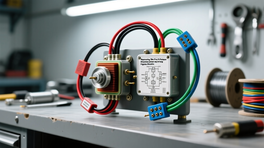
Introduction to the One Pickup Ignition System
When converting a classic vehicle from breaker-point ignition to an electronic setup, or replacing a faulty OEM distributor module, understanding the one pickup wiring diagram is critical. A 'one pickup' system refers to an ignition architecture that relies on a single magnetic pickup coil (stator) inside the distributor to trigger the ignition control module (ICM). Unlike modern distributorless systems that use separate crank and cam position sensors, the single magnetic pickup generates a raw AC voltage signal as the reluctor wheel's teeth pass the magnetic pole piece. This signal is then rectified and amplified by the ICM to switch the ignition coil's primary circuit.
While the concept is straightforward, the execution requires strict adherence to wire gauge specifications, shielding protocols, and grounding procedures. Electromagnetic interference (EMI) from high-voltage spark plug wires can easily induce false signals in an unshielded one pickup wiring diagram, leading to misfires, backfires, or complete module failure. This practical how-to guide will walk you through the precise installation, routing, and diagnostic procedures for a universal single-pickup ignition retrofit.
Essential Tools and Wire Specifications
Before cutting or crimping a single wire, ensure you have the correct materials. Using undersized wire or unshielded cables for the pickup circuit is the number one cause of post-installation failure. According to SAE J1128 standards for low-tension automotive wiring, voltage drop and heat resistance must dictate your AWG choices.
| Circuit Function | Recommended AWG | Wire Type / Insulation | Terminal / Connector |
|---|---|---|---|
| Pickup Coil Signal | 18 AWG | Shielded Twisted Pair (STP) | Weather-Pack 2-Pin Sealed |
| ICM to Ignition Coil (-) | 14 AWG | Cross-Linked Polyethylene (XLPE) | Female Spade (0.250'') |
| Ignition Coil (+) Feed | 12 AWG | XLPE / GXL | Ring Terminal (5/16'') |
| Main 12V Ignition Switch | 10 AWG | GXL High-Temp | Ring Terminal (5/16'') |
| Module Ground Path | 12 AWG | Flexible Copper Braid | Ring Terminal with Star Washer |
Step-by-Step Installation Guide
Step 1: Mounting and Grounding the Ignition Control Module
The ICM acts as a high-speed switch for the ignition coil's primary circuit, handling up to 8 amps of continuous current. This generates significant heat. Mount the module to a clean, flat, bare metal surface on the firewall or inner fender. Never mount it on painted metal or plastic.
- Scrape away all paint and primer from the mounting area using a wire wheel or sandpaper.
- Apply a generous layer of thermal heat sink compound (silicone-based dielectric grease is not a substitute for thermal compound) to the back of the module.
- Secure the module using stainless steel hardware and a star washer on the grounding tab to bite through any residual surface oxidation.
- Run a dedicated 12 AWG ground wire from the module's dedicated ground terminal directly to the engine block or battery negative terminal. Do not rely solely on the mounting bracket for the ground path.
Step 2: Wiring the Single Pickup Coil
The heart of the one pickup wiring diagram is the connection between the distributor's internal magnetic pickup and the ICM. The pickup coil typically features two wires (commonly colored Violet and Green in aftermarket setups like MSD, or Orange and Purple in classic Chrysler electronic ignitions).
- Route the shielded twisted pair (STP) wire from the ICM to the distributor grommet. Critical: Keep these signal wires at least 4 inches away from spark plug wires, the main alternator output cable, and the ignition coil high-tension wire to prevent EMI cross-talk.
- Connect the pickup wires to the ICM's designated signal pins. While some modules are not polarity-sensitive, maintaining the factory color code (e.g., Violet to Violet, Green to Green) ensures correct phasing and prevents the spark from firing on the exhaust stroke.
- Solder all connections inside the distributor cap or harness pigtail and seal them with adhesive-lined heat shrink tubing to prevent moisture ingress, which can alter the resistance of the signal circuit.
Step 3: Connecting the Ignition Coil and 12V Power
The ignition coil requires a solid 12V feed during cranking and running. Many classic vehicles use a ballast resistor wire in the factory harness to drop voltage to 9V for breaker-point systems. For a modern one pickup ignition retrofit, this must be bypassed or replaced.
- Run a new 10 AWG wire from a switched 12V ignition source (a relay triggered by the ignition switch is highly recommended to prevent voltage drop across the 40-year-old factory ignition switch).
- Connect the 12V feed to the positive (+) terminal of the ignition coil.
- Connect the 14 AWG primary trigger wire from the ICM's 'COIL-' terminal to the negative (-) terminal of the ignition coil.
- If your specific ICM requires a ballast resistor (common in older Ford Duraspark or Chrysler Orange Box one pickup wiring diagrams), wire a 1.5-ohm ceramic ballast resistor inline on the positive coil feed. Modern high-dwell modules typically do not require this.
One Pickup Wiring Diagram: Schematic Routing Map
To visualize the circuit flow, refer to this text-based schematic map of a standard 4-pin single pickup module:
- Pin 1 (B+ / BAT): Connected to Switched 12V Ignition (Relay Output).
- Pin 2 (GND): Connected to Engine Block via 12 AWG wire and Star Washer.
- Pin 3 (SIG +): Connected to Pickup Coil Wire A (Violet).
- Pin 4 (SIG -): Connected to Pickup Coil Wire B (Green).
- Coil (-) Output: Switched ground path to Ignition Coil Negative Terminal.
Diagnostic Testing and Troubleshooting
Even with a perfect physical installation, verifying the electrical parameters is mandatory before starting the engine. Use a high-impedance digital multimeter (DMM) to perform the following tests based on the Haynes Automotive Wiring Manual diagnostic protocols.
Pickup Coil Resistance Test
Disconnect the pickup harness from the ICM. Set your DMM to Ohms (Ω). Measure across the two pickup wires. A healthy single magnetic pickup coil should read between 400 and 800 ohms at room temperature. A reading of infinite resistance (OL) indicates an internal open circuit, while a reading below 300 ohms suggests shorted windings.
AC Voltage Output (Cranking Test)
Set your DMM to AC Volts (V~). Connect the probes to the pickup coil wires. Disable the ignition coil or remove the fuel pump relay to prevent the engine from starting. Crank the engine. The reluctor wheel passing the pickup magnet should generate a raw AC voltage signal. You should see a minimum of 1.0V to 2.5V AC while cranking. If the voltage is below 0.5V, the air gap between the pickup pole piece and the reluctor wheel is too wide, or the internal magnet has weakened.
Symptom-Cause-Fix Decision Tree
- Symptom: Engine backfires through the carburetor/throttle body upon cranking.
- Cause: Pickup coil polarity is reversed, or the distributor is 180 degrees out of phase.
- Fix: Swap the Green and Violet pickup wires at the ICM connector and recheck base ignition timing.
- Symptom: Engine starts but misfires severely above 2,500 RPM.
- Cause: EMI interference inducing false trigger signals in the one pickup wiring diagram signal wires.
- Fix: Verify shielded twisted pair wire is used. Ensure the shield drain wire is grounded only at the ICM end, not at the distributor end. Reroute wires away from HEI/CDI spark plug cables.
- Symptom: No spark, and the ignition coil (-) terminal reads constant 12V.
- Cause: The ICM is not switching the ground path. This is usually caused by a failed internal switching transistor or a missing module ground.
- Fix: Load-test the module ground wire with a test light. If the ground is solid and the pickup is generating AC voltage, replace the ICM.
Final Expert Insights
Mastering the one pickup wiring diagram is about respecting the low-voltage signal path. The magnetic pickup generates a fragile analog signal that must survive a noisy engine bay environment to trigger a high-current inductive load. By utilizing shielded cabling, dedicated ground planes, and proper thermal management for your ICM, your single-pickup ignition retrofit will deliver reliable, high-energy spark for thousands of miles. For further reading on high-voltage suppression and secondary ignition routing, consult the MSD Performance Technical Articles library.