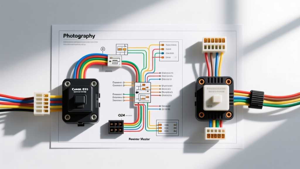
Introduction: The Master Switch as the Electrical Gateway
Replacing a failed master window control unit is rarely as simple as unplugging a connector and swapping the part. Modern vehicles utilize complex door modules, and the driver side power window switch wiring diagram serves as the critical roadmap for understanding how your vehicle manages high-current motor feeds and low-voltage data signals. Whether you are diagnosing a dead passenger window or an auto-up failure, selecting the correct replacement requires a deep understanding of internal switch architecture.
In this product comparison and selection guide, we analyze the internal circuitry, pinout configurations, and harness compatibility of OEM versus premium and budget aftermarket switches. By decoding the wiring schematics, you can avoid the common pitfalls of voltage drop, multiplex communication errors, and connector melt-downs that plague incorrect part installations.
Direct-Wire vs. Multiplex: Understanding Your Harness
Before selecting a replacement, you must identify which of the two primary wiring architectures your vehicle employs. The driver side power window switch wiring diagram will immediately reveal whether your system uses a traditional direct-wire setup or a modern multiplex network.
1. Traditional Direct-Wire Architecture (DPDT)
Common in vehicles prior to 2010 (and many heavy-duty trucks today), this system uses Double-Pole, Double-Throw (DPDT) mechanical relays inside the switch. The switch physically reverses the polarity on the two motor leads to dictate window direction. The wiring harness must carry the full stall current of the window motor (typically 15A to 25A) directly through the switch contacts.
2. Multiplex Architecture (LIN/CAN Bus & Resistor Ladders)
Modern vehicles route high current through a dedicated Door Control Module (DCM). The switch itself only handles milliamps of current, sending digital or analog signals to the DCM. Depending on the manufacturer, this is achieved via a Local Interconnect Network (LIN) bus or an analog resistor ladder network. Consulting the SAE International J2602 LIN Bus Specification reveals how sensitive these data lines are to internal switch resistance and capacitance.
Decoding the Driver Side Power Window Switch Wiring Diagram
Below is a reference pinout table for a standard 6-pin traditional direct-wire master switch (common in GM and Ford light trucks). Use this to verify your vehicle's harness before purchasing an aftermarket unit.
| Pin Cavity | Function | Standard OEM Wire Color | Wire Gauge (AWG) | Expected Voltage / State |
|---|---|---|---|---|
| A | Battery Feed (B+) | Orange / Red | 14 AWG | 12.6V (Constant) |
| B | Chassis Ground | Black | 14 AWG | 0.0V (<0.2V drop) |
| C | Motor Up Feed | Dark Blue | 16 AWG | 12V (Switch Actuated Up) |
| D | Motor Down Feed | Light Blue / Yellow | 16 AWG | 12V (Switch Actuated Down) |
| E | Illumination (+) | Brown / Gray | 18-20 AWG | 12V (Headlights ON) |
| F | RAP / Accessory Delay | Yellow / Pink | 18 AWG | 12V (Ignition OFF, Door Open) |
Note: Always verify pinouts against a Motorcraft OEM Wiring and Component Specifications manual for your specific year, as cavity letters can vary by connector manufacturer.
Product Selection Guide: OEM vs. Aftermarket Internal Architecture
When sourcing a replacement, the external plastic bezel might look identical, but the internal engineering dictates longevity and safety. Here is how OEM, Premium Aftermarket, and Budget switches compare when dissected against the wiring diagram requirements.
| Feature | Genuine OEM | Premium Aftermarket | Budget / Economy Aftermarket |
|---|---|---|---|
| Internal Busbars | Stamped copper alloy, rated for 25A continuous. | Copper-clad aluminum, rated for 20A. | Thin-gauge 18 AWG jumper wires soldered to PCB. |
| Contact Material | Silver-cadmium oxide (resists arcing and pitting). | Silver-nickel alloy. | Bare copper (prone to rapid oxidation and carbon buildup). |
| Connector Tolerance | Exact match to Delphi Automotive Metri-Pack Connector Systems specs. | Slight variance; may require terminal drag adjustment. | Oversized housings; causes pin push-out and intermittent faults. |
| Multiplex Resistors | 1% tolerance metal film resistors. | 5% tolerance carbon film resistors. | Unmarked resistors; causes BCM logic errors. |
The Resistor Ladder Pitfall: Chrysler & Jeep Case Study
If your driver side power window switch wiring diagram shows a 4-pin or 5-pin connector with a single 'Multiplex' or 'Mux' wire, your vehicle likely uses a resistor ladder network. When you press a button, the switch routes the 5V reference signal through a specific internal resistor (e.g., 330Ω for Driver Up, 680Ω for Passenger Down). The Body Control Module (BCM) reads the voltage drop to determine which window to move.
The Aftermarket Failure Mode: Budget switches often use cheap resistors with wide tolerances or degrade rapidly under thermal cycling. If the BCM expects a 2.5V signal for 'Passenger Up' but the cheap resistor yields 2.8V due to heat drift, the BCM will ignore the command or trigger a 'Window Switch Circuit Range/Performance' DTC (Diagnostic Trouble Code). Always select OEM or premium tier switches for resistor-ladder multiplex systems.
Troubleshooting Pinout Mismatches and Voltage Drop
Before condemning a new switch or a window motor, use a digital multimeter (DMM) to perform the following diagnostic checks based on your wiring diagram:
- The 0.5V Drop Test: With the switch actuated and the motor stalled (holding the button while the window is fully rolled up), measure the voltage drop across the switch's internal contacts (from the B+ pin to the Motor Feed pin). A drop greater than 0.5V indicates pitted internal contacts or undersized aftermarket busbars. This robs the motor of torque, leading to slow window travel and eventual regulator failure.
- Ground Integrity Check: Measure the voltage between the switch's dedicated Ground pin (Pin B) and the vehicle's bare chassis metal. If you read more than 0.1V, the issue is a corroded door-hinge ground strap, not the switch. High resistance on the ground circuit will backfeed into the illumination circuit, causing the switch LEDs to dim when the window motor engages.
- Terminal Push-Out Inspection: Budget aftermarket switches often have poorly molded connector shrouds. When mating the female harness connector to the male switch pins, listen for the secondary lock 'click'. If a pin pushes backward into the housing, the circuit will remain open. Use a terminal pick to reset the locking barb on the female Metri-Pack 280 terminal before reinstalling.
Final Selection Verdict
When utilizing a driver side power window switch wiring diagram to source a replacement, match the internal architecture to your vehicle's generation. For traditional direct-wire systems, prioritize switches with stamped copper busbars and silver-alloy contacts to handle the 20A motor stall currents without melting the connector housing. For modern LIN-bus or resistor-ladder multiplex systems, never compromise on OEM or premium-tier electronics; the micro-tolerances required by the BCM will quickly expose the flaws of budget carbon-film resistors, leaving you with intermittent window operation and phantom electrical drains.