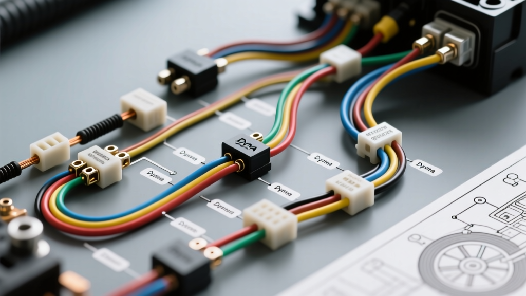
Introduction to the Dyna S Electronic Ignition System
Upgrading from mechanical breaker points to a solid-state Hall effect system is one of the most reliable modifications you can perform on a classic V-Twin motorcycle. The Dyna S ignition system, manufactured by Dynatek, replaces the unreliable points and condenser setup found on Harley-Davidson Shovelhead, Panhead, Ironhead, and early Evolution engines. However, installing the hardware is only half the battle; understanding the dyna s ignition wiring diagram is critical to ensuring consistent spark, proper timing, and module longevity.
This complete wiring walkthrough covers the standard Dual Fire (DS-1 and DS-2) configurations. Unlike single-fire systems that require dual coils and complex cam-position sensors, the Dual Fire Dyna S utilizes a waste-spark principle, firing both spark plugs simultaneously. This simplifies the harness, reduces potential failure points, and maintains OEM-style coil compatibility, provided the primary resistance is correctly matched.
Core Components and Wire Color Codes
The standard Dual Fire Dyna S module features a simplified three-wire harness. There is no need for a separate ballast resistor or complex ECU pinout mapping. Below is the definitive color code reference for the module's pigtail.
| Wire Color | Function | Destination / Connection Point | Operating Voltage |
|---|---|---|---|
| Red | Switched 12V+ Power | Ignition Coil (+) Terminal / Kill Switch Output | 11.5V - 14.2V DC |
| White | Trigger / Coil Negative | Ignition Coil (-) Terminal / Points Wire | Pulsing 0V - 12V |
| Black | System Ground | Engine Case / Clean Chassis Ground | 0V (Reference) |
Step-by-Step Dyna S Ignition Wiring Diagram Walkthrough
To execute this wiring diagram properly, you must abandon the 'cut-and-twist' methods often found in amateur garages. Every connection must be soldered and sealed with adhesive-lined heat shrink to prevent moisture ingress and vibration-induced resistance.
1. Switched 12V Power Routing (Red Wire)
The Red wire requires a clean, switched 12-volt source that is active only when the ignition is ON and the handlebar kill switch is in the RUN position.
- Trace the Circuit: Battery Positive → Main Circuit Breaker → Ignition Switch → Kill Switch → Coil (+) Terminal.
- The Splice: The Red wire from the Dyna S module should be spliced directly into the wire leading to the positive terminal of the ignition coil.
- Voltage Drop Warning: Use a digital multimeter (DMM) to measure voltage at the Coil (+) terminal while the starter is cranking. If the reading drops below 10.5V, the Hall effect sensor inside the Dyna S module will fail to trigger. Clean all switch contacts and upgrade the ignition switch wiring to 14 AWG if excessive voltage drop is detected.
2. Ignition Coil Negative Trigger (White Wire)
The White wire acts as the electronic switch, replacing the mechanical points. It connects directly to the negative terminal of the ignition coil.
- Connection: Attach the White wire to the Coil (-) terminal using a 1/4-inch insulated female spade connector. Do not overtighten the nut, as the bakelite or epoxy casing on older coils can crack.
- Tachometer Integration: If your motorcycle is equipped with an OEM analog tachometer, its trigger wire also connects to this Coil (-) terminal. The Dyna S module safely handles the inductive kickback required to drive standard analog tachometers without the need for a separate tachometer adapter.
- Crucial Coil Requirement: The ignition coil must have a primary resistance between 3.0 and 3.2 ohms. Using a high-performance 1.5-ohm coil will draw excessive amperage (over 8 amps), instantly destroying the output transistor inside the Dyna S module.
3. Chassis and Engine Grounding (Black Wire)
The Black wire provides the reference ground for the module's internal logic board.
- Mounting Point: Do not ground this wire to the battery negative terminal directly, as this can create a ground loop that introduces alternator whine into the ignition timing. Instead, ground it directly to the engine case or the primary inner cover.
- Hardware: Remove all paint, powder coat, or corrosion from the grounding surface. Use a stainless steel star washer between the ring terminal and the bare metal to bite through any microscopic oxidation. Apply a dab of dielectric grease over the completed connection to prevent galvanic corrosion.
Wire Gauge, Terminal, and Component Specifications
Adhering to SAE J1128 standards for low-tension primary cable ensures the harness can withstand engine bay temperatures and chemical exposure.
| Component / Wire | Specification | Material / Type |
|---|---|---|
| Main Power & Ground | 16 AWG | SAE J1128 GXL (Cross-linked polyethylene, 125°C rated) |
| Coil Trigger (White) | 18 AWG | SAE J1128 TXL (Thin-wall, high-temp) |
| Coil Terminals | 1/4' Female Spade | Nylon fully-insulated, brass internal sleeve |
| Ground Terminals | #10 Ring Terminal | Non-insulated copper, brazed seam |
| Spark Plug Wires | 7mm or 8mm | Carbon-core or Spiral-core (Suppression type only) |
RF Interference and Spark Plug Wire Routing
A frequent cause of erratic timing and premature module failure in electronic ignitions is Electromagnetic Interference (EMI). The Hall effect sensor inside the Dyna S stator plate is highly sensitive to radio frequency noise.
- Never use solid copper-core spark plug wires. Copper wire acts as an antenna, broadcasting the high-voltage spark event directly back into the ignition harness.
- Use only carbon-impregnated linen core or spiral-wound stainless steel suppression wires (e.g., Taylor Spiro-Pro or Accel 8mm). These wires provide a minimum of 500 ohms per foot of resistance to choke EMI radiation.
- Route the spark plug wires at least two inches away from the Dyna S module harness, the stator wires, and the voltage regulator to prevent inductive cross-talk.
Stator Plate Installation and Air Gap Verification
While not strictly part of the external wiring harness, the internal wiring of the Hall sensor relies entirely on physical alignment. The Dyna S rotor features two neodymium magnets that trigger the sensor as the camshaft rotates.
- Air Gap Specification: The clearance between the edge of the rotor magnets and the face of the Hall effect sensor must be between 0.030' and 0.060' (0.76mm - 1.52mm).
- Measurement: Use a non-magnetic brass feeler gauge to set this gap. If the gap is too wide, the magnetic field will be too weak to trigger the module at low cranking speeds. If it is too tight, mechanical runout could cause the rotor to strike the sensor, destroying the unit.
Multimeter Diagnostics and Troubleshooting Tree
When diagnosing a no-spark condition, follow this logical decision tree using a standard digital multimeter. This isolates the fault without requiring expensive oscilloscopes.
- Step 1: Verify Power and Ground
- Set DMM to DC Volts. Probe Red wire (back-probe) and Black wire.
- Ignition ON: Reading should be 12.0V - 12.6V.
- Fault: If 0V, check main breaker, ignition switch, and kill switch.
- Step 2: Test Coil Primary Resistance
- Disconnect coil wires. Set DMM to Ohms (Ω).
- Probe Coil (+) and Coil (-). Reading must be 3.0Ω - 3.2Ω.
- Fault: If reading is 1.5Ω, replace coil immediately to save the module.
- Step 3: The 'Pull-Down' Trigger Test
- Reconnect Coil (+) and Red wire. Disconnect White wire from Coil (-).
- Set DMM to DC Volts. Probe the disconnected White wire and engine ground.
- Ignition ON: DMM should read ~12V (internal pull-up resistor).
- Momentarily ground the White wire to the engine case. You should see a spark at the plugs, and the DMM should drop to 0V.
- Fault: If the White wire reads 0V before grounding, the internal output transistor is shorted (module is dead). If it reads 12V but no spark occurs when grounded, the ignition coil or high-tension leads are faulty.
Authoritative References and Further Reading
For deeper electrical theory and OEM-specific harness routing, consult the following industry-standard resources:
- Dynatek Official Installation Guidelines - Manufacturer specifications for coil resistance and timing procedures.
- SAE J1128: Low Tension Primary Cable Standard - Wire insulation and temperature rating requirements.
- Haynes Harley-Davidson Shovelhead & Panhead Service Manual - Reference for OEM ignition switch pinouts and handlebar kill switch continuity testing.