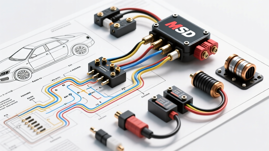
Project Overview: Upgrading to MSD Capacitive Discharge
Upgrading from a factory points distributor, HEI module, or early TFI system to an MSD Capacitive Discharge (CD) ignition is one of the most effective modifications for high-RPM reliability and throttle response. However, the most common point of failure in aftermarket ignition projects is not the hardware itself, but the vehicle wiring integration. Relying on MSD ignition wiring diagrams straight from the box without accounting for factory voltage drop, ballast resistors, and tachometer incompatibilities will result in misfires, melted harnesses, or a no-start condition.
This guide focuses on the industry-standard MSD 6AL (Part No. 6425) and provides the exact wiring schematics, relay bypass protocols, and pinout configurations required for a bulletproof upgrade project.
Core MSD 6AL (6425) Wiring Pinouts & Color Codes
The MSD 6AL utilizes a multi-pin connector with specific color-coded leads. Understanding the function and required gauge for each wire is critical before cutting a single factory wire. According to MSD Performance Technical Specifications, the primary harness is broken down into heavy-gauge power feeds and low-voltage trigger/signal wires.
| Wire Color | Recommended AWG | Function | Destination / Notes |
|---|---|---|---|
| Heavy Red | 8 AWG (Upgraded) | Main +12V Power | Direct to Battery (+) via 40A Relay |
| Heavy Black | 8 AWG (Upgraded) | Main Ground | Direct to Engine Block or Battery (-) |
| Red | 16 AWG | Switched 12V Trigger | Ignition Switch 'Run' position (Post-Ballast) |
| Orange | 14 AWG | Coil Positive (+) | Ignition Coil (+) Terminal |
| White | 18 AWG | Points / Amplifier Trigger | Coil (-) or Points (Only if NOT using Magnetic Pickup) |
| Violet | 18 AWG | Magnetic Pickup (+) | Distributor / Crank Trigger Pickup (+) |
| Green | 18 AWG | Magnetic Pickup (-) | Distributor / Crank Trigger Pickup (-) |
The Critical Flaw: Why You Must Bypass Factory Ignition Wiring
The most frequent mistake in MSD upgrades is splicing the Heavy Red wire directly into the factory ignition feed wire. Factory ignition circuits are typically wired with 16 AWG or 18 AWG wire, designed to supply a maximum of 4 to 6 amps to a stock coil. Under high-RPM load, an MSD 6AL can draw peak currents exceeding 14 amps. Pushing this amperage through a long, undersized factory wire results in severe voltage drop, starving the CD box and causing high-RPM misfires or thermal melting of the OEM harness.
Per SAE J1128 Low Tension Primary Cable Standards, you must use a dedicated heavy-gauge circuit with a Bosch-style relay to deliver stable voltage directly from the battery.
Step-by-Step 40A Relay Integration Diagram
To properly power the MSD 6AL, integrate a standard 4-pin/5-pin automotive relay (Bosch type) using the following schematic:
- Pin 30 (Power In): Run 8 AWG wire directly from the Battery Positive terminal. Install an inline 40A MAXI fuse within 18 inches of the battery.
- Pin 87 (Power Out): Run 8 AWG wire from Pin 87 directly to the MSD Heavy Red wire. Use a sealed ring terminal and heat-shrink butt connector.
- Pin 85 (Ground): Run 14 AWG wire to a clean, bare-metal chassis ground or directly to the battery negative.
- Pin 86 (Trigger): Connect 16 AWG wire to the vehicle's OEM switched 12V ignition source. This low-amp signal simply activates the relay coil, allowing the 8 AWG circuit to power the MSD box.
Expert Tip: Always use closed-barrel crimps with adhesive-lined heat shrink for the 8 AWG connections. Soldering high-amperage automotive wires in high-vibration environments can lead to brittle fractures and intermittent open circuits.
Coil Negative Routing & The Ballast Resistor Trap
Routing the Coil Negative (-) terminal correctly depends entirely on your trigger source. Furthermore, older vehicles (especially Chrysler/Mopar and AMC) utilize a factory ballast resistor or resistance wire that drops voltage to 7V-9V before it reaches the coil.
1. The Ballast Resistor Bypass
The MSD Red (Switched 12V) wire requires a full 12 volts to operate the internal microprocessor and trigger the CD circuit. If you tap into the factory coil positive wire on a Mopar, you will only feed the MSD 7 volts, causing it to shut down. You must bypass the factory ballast resistor by running a new 16 AWG wire from the ignition switch 'Run' terminal directly to the MSD Red wire and the relay Pin 86.
2. Routing Coil Negative (Points vs. Magnetic Pickup)
- Using Factory Points: Connect the MSD White wire to the Coil Negative terminal. The points act as a ground switch to trigger the MSD box. Remove the factory condenser; it is no longer needed and will interfere with the CD signal.
- Using MSD Pro-Billet / Magnetic Pickup: Do NOT connect the White wire. Connect the Violet and Green wires to the distributor's magnetic pickup. The Coil Negative terminal is grounded internally by the distributor's pickup assembly or left floating depending on the specific MSD distributor model. Consult your distributor manual to verify if the Coil (-) requires a ground strap.
Magnetic Pickup Polarity & Phasing Verification
When wiring the Violet (+) and Green (-) wires to a magnetic pickup (such as a crank trigger or Pro-Billet distributor), polarity matters. If wired in reverse, the engine may start but will exhibit erratic timing, severe backfiring, or fail to rev past 3,000 RPM. If the engine backfires through the carburetor upon initial startup, simply swap the Violet and Green wires at the MSD connector.
Tachometer & Rev Limiter Wiring Specifics
The MSD 6AL features a built-in soft-touch rev limiter controlled by dip switches or plug-in pill chips. However, it does not output a standard 12V square-wave tachometer signal directly from the box.
If your vehicle uses an aftermarket EFI system or a modern digital dash expecting a 12V square wave, tapping the Coil Negative will result in a bouncing or dead tachometer needle due to the 400-voltage multi-spark output of the MSD. You must install an MSD Tach Adapter (PN 8910 or 8920) between the Coil Negative and the tachometer signal wire to step down and square off the pulse.
Troubleshooting Common Upgrade Failures
Use this diagnostic matrix to resolve common issues encountered during MSD ignition modification projects.
| Symptom | Root Cause | Verification & Fix |
|---|---|---|
| Engine dies when starter is released | MSD Red wire wired to 'Start' terminal instead of 'Run', or Ballast Resistor still in circuit. | Test MSD Red wire with multimeter in 'Run' (Key On, Engine Off). Must read >11.5V. Bypass ballast resistor. |
| High-RPM Misfire / Stumbling | Voltage drop on Heavy Red wire; factory harness used instead of relay bypass. | Measure voltage at Heavy Red wire while cranking and at 4000 RPM. Install 8 AWG relay bypass circuit. |
| Severe Backfire / Won't Rev | Magnetic Pickup polarity reversed (Violet/Green swapped). | Swap Violet and Green wires at the MSD harness connector. |
| Tachometer Needle Bouncing | Tach signal wire connected directly to Coil (-) without adapter. | Install MSD PN 8910 Tach Adapter to filter the multi-spark CD voltage. |
| No Spark / Dead Box | Heavy Black ground connected to painted chassis or intake manifold. | Relocate Heavy Black ground directly to engine block or battery negative using a star washer. |
By adhering to these upgraded wiring schematics and abandoning the reliance on undersized factory harnesses, your MSD ignition modification will provide consistent, high-energy spark across the entire RPM range. For further reference on high-voltage suppression and spark plug gap specifications for CD ignitions, consult the MSD Performance Official Wiring Resources library.