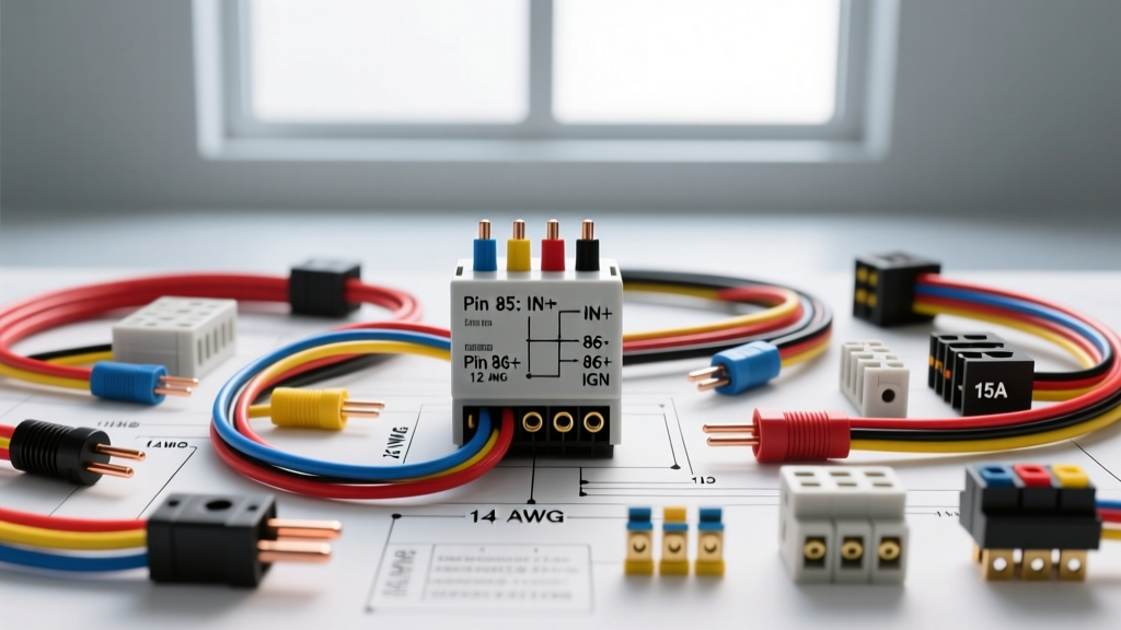
Introduction to Motohorn Electrical Architecture
Upgrading a motorcycle or light vehicle to a high-decibel dual-tone air horn system requires a complete re-evaluation of the OEM electrical circuit. The standard motohorn wiring diagram provided by aftermarket manufacturers often oversimplifies the integration process, leading to voltage drop, relay chatter, and in severe cases, melted OEM switchgear. Stock horn buttons and factory wiring harnesses are typically designed for 3A to 5A electromagnetic disc horns, utilizing 18 AWG or 20 AWG primary wire. In contrast, a heavy-duty Motohorn dual-air compressor draws between 15A and 22A under peak load. This technical specification reference details the precise electrical architecture, wire gauge requirements, relay logic, and IP67 waterproofing protocols necessary to safely integrate a high-draw air horn system into modern 12V DC automotive and motorcycle platforms.
Core Electrical Specifications & Current Draw
Before routing wires or selecting fuses, it is critical to understand the electrical load profile of a standard Motohorn dual-trumpet compressor. Unlike steady-state loads, air compressors exhibit a high inrush current when the motor initially engages, followed by a running current that fluctuates based on back-pressure in the air line.
| Parameter | Specification | Engineering Notes |
|---|---|---|
| Operating Voltage | 12V - 14.4V DC | System must maintain >11.5V at the compressor under load to prevent thermal cutoff. |
| Inrush Current (Peak) | 22A - 25A | Occurs during the first 0.5 seconds of motor startup before back-pressure builds. |
| Running Current | 15A - 18A | Steady-state draw at 90 PSI to 110 PSI operating pressure. |
| Duty Cycle | 15% @ 100 PSI | Compressor requires a 45-second cool-down for every 8 seconds of operation. |
| Recommended Fuse | 25A ATO/ATC Blade | Must be placed within 18 inches of the battery positive terminal per SAE J1111. |
Standard 4-Pin Bosch Relay Pinout Configuration
Because the OEM horn switch cannot handle the 18A running current, a dedicated power circuit controlled by an ISO Mini 4-Pin relay (commonly referred to as a Bosch-style relay) is mandatory. The relay acts as an electrically isolated switch, allowing the low-current OEM horn button to trigger the high-current compressor circuit.
Relay Terminal Mapping and Circuit Logic
- Pin 30 (Common / Power In): Connected directly to the vehicle battery positive (+) terminal via an inline 25A ATO fuse. This circuit must utilize 12 AWG SXL wire to minimize voltage drop over the distance from the battery to the relay.
- Pin 87 (Normally Open / Load Out): Connected to the positive terminal of the Motohorn compressor. When the relay coil is energized, the internal contactor bridges Pin 30 and Pin 87, delivering full battery voltage to the compressor.
- Pin 85 (Coil Ground): Connected to a clean, unpainted chassis ground or directly to the battery negative (-) terminal. Utilizing 16 AWG wire is sufficient for the coil ground circuit.
- Pin 86 (Coil Trigger): Connected to the OEM horn switch output wire. When the driver presses the horn button, 12V is sent to Pin 86, energizing the electromagnetic coil and pulling the Pin 30-87 contactor closed.
For vehicles utilizing a ground-side switched horn circuit (common in many modern CAN-bus motorcycles and European automobiles), Pin 86 must be tied to a switched 12V ignition source, and Pin 85 must be routed to the OEM horn button output, which completes the ground path when pressed.
Wire Gauge Selection and SAE Standards
Selecting the correct wire gauge is paramount to preventing resistive heating and voltage drop. According to the SAE J1128 standard for Low Tension Primary Cable, automotive wiring must utilize cross-linked polyethylene (SXL or TXL) insulation to withstand high under-hood temperatures and resist chemical degradation. Standard PVC-insulated wire is unacceptable for engine bay routing due to its lower melting point and poor abrasion resistance.
| Circuit Segment | AWG Size | Insulation Type | Max Length (One Way) |
|---|---|---|---|
| Battery to Inline Fuse | 10 AWG | SXL | 18 Inches |
| Fuse to Relay Pin 30 | 12 AWG | SXL | 48 Inches |
| Relay Pin 87 to Compressor (+) | 12 AWG | SXL | 60 Inches |
| Compressor (-) to Chassis Ground | 12 AWG | SXL | 24 Inches |
| OEM Trigger to Relay Pin 86 | 18 AWG | TXL | N/A (Low Current) |
Voltage Drop Calculation
To ensure the Motohorn compressor receives adequate voltage, the voltage drop across the power and ground circuits must not exceed 3% (0.36V on a 12V system). Using the standard copper resistance formula for DC circuits:
Voltage Drop = (2 x K x I x L) / CM
Where K is the resistivity of copper (12.9 ohms per mil-foot at 50°C), I is current (18A), L is one-way wire length in feet (e.g., 8 feet), and CM is the circular mil area of 12 AWG wire (6530). For an 8-foot run of 12 AWG wire carrying 18A, the voltage drop is approximately 0.56V. While slightly above the ideal 3% threshold, it remains well within the operational tolerance of the Motohorn motor. If the routing exceeds 8 feet, upgrading the main power feed to 10 AWG is strictly required.
Modern CAN-Bus Integration and Bypass Protocols
Integrating a motohorn wiring diagram into modern motorcycles (such as the BMW R1250GS, Harley-Davidson Touring models, or late-model Ducati Multistrada) presents a unique challenge due to Body Control Modules (BCM) and CAN-bus networks. These systems monitor the current draw on the OEM horn circuit. If the BCM detects an open circuit (because you disconnected the OEM horn) or an over-current condition (if you attempt to power a relay coil directly from a solid-state BCM output without a flyback diode), it will trigger a dashboard fault code and disable the circuit.
The Flyback Diode Requirement
When tapping a BCM-controlled horn trigger wire to feed Relay Pin 86, the electromagnetic collapse of the relay coil generates a high-voltage reverse polarity spike (inductive kickback). This spike can instantly destroy the BCM's internal solid-state switching transistor. To prevent this, a 1N4001 or 1N5400 flyback diode must be soldered in parallel across the relay coil terminals (Pin 85 and Pin 86), with the diode's cathode (striped end) facing the 12V trigger source. This creates a localized loop that safely dissipates the inductive spike.
IP67 Waterproofing and Termination Specifications
Motorcycles and off-road vehicles are subjected to high-pressure water ingress and road salt. Standard vinyl crimp connectors will corrode and fail within a single season. All terminations in the motohorn wiring harness must adhere to IP67 waterproofing standards.
- Battery and Ground Ring Terminals: Use adhesive-lined marine-grade heat shrink ring terminals. The internal polyamide adhesive melts during the shrinking process, creating a watertight seal against the wire strands. Torque battery terminal bolts to manufacturer specifications (typically 8-10 Nm for M6 bolts).
- Relay Connections: Utilize a sealed relay socket with integrated silicone weather seals rather than pushing individual spade connectors onto the relay tabs. If individual tabs are used, they must be fully insulated silicone boots.
- Compressor Interface: The connection at the Motohorn compressor should utilize a Deutsch DT Series 2-pin connector. These connectors feature silicone grommles and secondary wedge locks that prevent terminal back-out and moisture intrusion, making them the industry standard for heavy-duty automotive and marine applications.
Troubleshooting Matrix: Symptom, Cause, and Resolution
Even with a meticulously executed wiring diagram, environmental factors and component variances can lead to operational anomalies. Use the following diagnostic matrix to troubleshoot common Motohorn installation issues.
| Symptom | Probable Electrical Cause | Technical Resolution |
|---|---|---|
| Relay Chatter (Rapid Clicking) | Severe voltage drop on the trigger circuit (Pin 86) caused by high resistance in the OEM horn switch or corroded connectors. | Measure voltage at Pin 86 while the button is held. If below 10.5V, install a secondary micro-relay to buffer the trigger signal or clean OEM switch contacts. |
| Compressor Hums but Doesn't Pump | Voltage at the compressor drops below 10V under load, causing the motor to stall before building sufficient torque to cycle the piston. | Upgrade main power and ground wires from 12 AWG to 10 AWG. Verify battery health and alternator output. Check for loose crimps at the ring terminals. |
| Horn Sounds Weak / Pitch is Low | Moisture ingress in the trumpet bells or inadequate airflow due to restrictive air lines. | Ensure trumpets are mounted pointing slightly downward to drain condensation. Verify the air line ID is at least 1/4-inch and free of sharp kinks. |
| BCM Fault Code / Dash Warning | CAN-bus system detected missing OEM horn load or inductive kickback damaged the BCM driver. | Install a CAN-bus load equalizer resistor in parallel with the OEM horn circuit, or verify the flyback diode is correctly oriented across the relay coil. |
Final Verification and Safety Protocols
Upon completion of the physical wiring, always perform a dry-run test with the vehicle's ignition on but the engine off. Use a digital multimeter to verify that 12.6V is present at Pin 30 of the relay and that the trigger signal successfully reaches Pin 86. Once verified, engage the compressor and measure the voltage directly at the compressor's positive terminal while it is running. If the inline ATO fuse holds and the voltage remains above 11.5V, the motohorn wiring integration meets all professional automotive electrical standards. Finally, secure all wiring harnesses with UV-resistant nylon cable ties and split-loom corrugated tubing to protect against abrasion and exhaust heat.