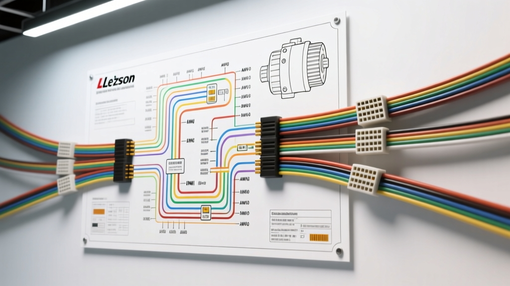
Integrating Industrial Motors into Automotive Chassis
When executing a custom electric vehicle (EV) conversion or retrofitting a classic hot rod with modern amenities, builders frequently turn to robust industrial components. A highly sought-after reference in the custom automotive electrical space is the wiring diagram for Leeson electric motors, particularly their 12V and 24V Permanent Magnet DC (PMDC) lines. While Leeson primarily designs these motors for agricultural, marine, and industrial applications, their high torque-to-weight ratio, continuous duty ratings, and durable brush assemblies make them ideal for automotive auxiliary systems. In an EV swap where the internal combustion engine (ICE) is removed, you lose the mechanical belt-driven power steering pump and vacuum brake booster. To restore these critical safety systems, builders utilize Leeson DC motors to drive hydraulic steering pumps and vacuum canisters.
However, integrating an industrial motor into a vehicle's 12V or 24V electrical architecture requires strict adherence to automotive wiring standards. Unlike stationary industrial setups, a vehicle is subjected to severe vibration, thermal cycling, and corrosive environments. This comprehensive walkthrough details the exact wire gauges, automotive relay pinouts, and pulse-width modulation (PWM) integration required to safely wire a Leeson PMDC motor for automotive auxiliary hydraulics.
High-Current Power Distribution and AWG Sizing
The most common failure point in custom EV auxiliary wiring is undersized cabling. A Leeson 12V DC hydraulic pump motor can draw anywhere from 30A to 65A continuously, with inrush currents exceeding 200A during startup. If you size your wiring based solely on the continuous amperage, the voltage drop during inrush will starve the motor, causing excessive heat and premature brush wear. According to SAE J1128 standards for low-tension primary cable, automotive wire must be rated for higher thermal loads and strand counts to withstand chassis vibration.
For the high-current side of the Leeson motor circuit, you must use SAE-rated cross-linked polyethylene (XLPE) insulated copper wire. Standard PVC wire will melt near exhaust components or during prolonged high-load steering maneuvers. Below is the required AWG sizing chart based on the total round-trip circuit length (positive and ground) and maximum continuous draw.
| Motor Continuous Draw | Circuit Length (Round Trip) | Minimum AWG Size (SAE) | Recommended Fuse (MIDI/Mega) |
|---|---|---|---|
| 30A - 40A | Under 10 ft | 6 AWG | 60A |
| 30A - 40A | 10 ft - 20 ft | 4 AWG | 60A |
| 45A - 65A | Under 10 ft | 4 AWG | 80A |
| 45A - 65A | 10 ft - 20 ft | 2 AWG | 100A |
The Control Circuit: Contactors and PWM Integration
A standard 40A Bosch-style automotive relay is entirely insufficient for switching the main power to a Leeson hydraulic pump motor. The inrush current will quickly pit and weld the internal contacts of a standard relay, causing the motor to run continuously even when the ignition is off—a catastrophic failure mode that can lead to an electrical fire. Instead, the wiring diagram must incorporate a high-current DC contactor (such as a Gigavac or Albright solenoid) paired with a PWM motor controller.
Using a PWM controller is critical for automotive steering applications. If a Leeson motor runs at 100% duty cycle continuously, the hydraulic fluid will overheat, and the motor will draw maximum current, draining your EV battery pack rapidly. A PWM controller reads the steering column torque sensor (or a simple pressure switch) and modulates the Leeson motor speed, maintaining hydraulic pressure while reducing average current draw by up to 60%.
Step-by-Step Wiring Diagram Walkthrough
Follow this precise sequence to wire the Leeson PMDC motor into your vehicle's electrical system. Always disconnect the main battery pack and 12V accessory battery before beginning.
1. High-Current Power and Ground Routing
- Positive Feed (Red 2 AWG): Run a 2 AWG SAE XLPE red wire from the positive terminal of the 12V accessory battery (or DC-DC converter) to an 80A Mega fuse holder. Mount the fuse within 18 inches of the battery source.
- Contactor Input: From the fuse, route the red wire to the primary input stud (Terminal 30 equivalent) on the DC contactor.
- Motor Positive (Red 4 AWG): Run a 4 AWG red wire from the contactor's output stud (Terminal 87 equivalent) directly to the Leeson motor's A1 (+) terminal.
- Motor Ground (Black 4 AWG): Route a 4 AWG black wire from the Leeson motor's A2 (-) terminal to a dedicated, clean chassis ground. Use a brass grounding lug, scrape away all paint and powder coating, and secure with a Grade 8 bolt and star washer. Apply dielectric grease over the completed joint to prevent galvanic corrosion.
2. Control Circuit and Relay Integration
The control circuit uses standard 12 AWG automotive primary wire (GXL or TXL) to trigger the contactor coil and feed the PWM logic board.
- Ignition Source (Yellow 12 AWG): Tap into an ignition-switched 12V source (e.g., the ignition switch "Run" position). Route this to the PWM controller's main power input.
- PWM to Contactor Coil (Blue 12 AWG): The PWM controller acts as the ground switch for the contactor. Run a blue wire from the contactor's positive coil terminal to a switched 12V source. Run a second blue wire from the contactor's negative coil terminal to the PWM controller's "Motor Enable" or "Ground Switch" output.
- Signal Feedback (White 18 AWG): If your PWM requires a tachometer or voltage feedback signal to prevent runaway RPMs, connect the shielded white signal wire to the Leeson motor's optional tach output terminal (if equipped) or rely on the controller's internal back-EMF sensing.
Leeson PMDC Motor Terminal Pinout Reference
Leeson DC motors utilize standardized NEMA terminal markings. Understanding these pinouts is essential to ensure correct rotation and prevent damage to the PWM controller. According to NEMA MG-1 Standards, reversing the armature leads relative to the field leads reverses motor direction. In a PMDC motor, the field is permanent, so simply swapping A1 and A2 will reverse the hydraulic pump rotation—which can cause immediate cavitation and pump destruction.
| Terminal Marking | Function | Automotive Wire Color | Connection Target |
|---|---|---|---|
| A1 | Armature Positive (+) | Red (4 AWG) | Contactor Output / PWM (+) |
| A2 | Armature Negative (-) | Black (4 AWG) | Chassis Ground / PWM (-) |
| S1 / S2 | Thermal Overload Switch (Optional) | Yellow / Green (18 AWG) | PWM Fault Input / Dash Warning Light |
| Tach | Hall Effect / Tachometer Output | White (Shielded 18 AWG) | PWM Feedback Loop |
Real-World Troubleshooting and Failure Modes
Even with a perfect wiring diagram for Leeson electric motors, automotive environments introduce unique variables. Here is a diagnostic decision tree for common integration failures:
Symptom: Motor Stalls Under Heavy Steering Load
Cause: Excessive voltage drop in the ground circuit. The chassis of a classic car or custom EV often has poor electrical continuity due to rust, polyurethane bushings, or powder-coated mounting brackets.
Fix: Perform a voltage drop test using a digital multimeter. Place the positive probe on the motor's A2 terminal and the negative probe on the battery's negative post while the motor is under load. A reading above 0.2V indicates a ground fault. Install a dedicated 2 AWG ground cable directly from the motor casing to the battery negative terminal, bypassing the chassis entirely.
Symptom: Contactor Chatters or Clicks Rapidly
Cause: The PWM controller is triggering the contactor coil at a high frequency, or there is insufficient current to hold the contactor closed due to undersized control wiring.
Fix: Verify that the PWM is outputting a clean DC ground to the contactor coil, not a pulsed signal. If the PWM uses a solid-state relay (SSR) for switching, ensure it is rated for the inductive load of the contactor coil. Install a flyback diode (e.g., 1N5408) across the contactor coil terminals (band facing positive) to suppress inductive voltage spikes that can destroy the PWM's internal switching transistors.
Symptom: Motor Runs Hot and Shuts Down Intermittently
Cause: Thermal overload switch (S1/S2) tripping due to lack of airflow. Industrial Leeson motors are often TEFC (Totally Enclosed Fan Cooled) and rely on the motor's shaft speed to move air over the casing. In hydraulic pump applications, the motor may run at low RPM via the PWM for extended periods, eliminating active cooling.
Fix: Relocate the motor to an area with ambient airflow, or install a dedicated 12V cooling fan directed at the Leeson motor's finned casing. Alternatively, bypass the internal thermal switch and rely on the PWM controller's internal thermal modeling and current-limiting algorithms to prevent burnout, provided you are monitoring fluid temperatures.
Authoritative References
When designing high-current automotive electrical systems, always consult the latest engineering standards to ensure safety and reliability. For further reading on automotive wire ratings and DC motor specifications, refer to Littelfuse Application Notes on high-current DC fuse coordination, and ensure your battery isolation systems meet all relevant FMVSS guidelines for electric vehicle conversions.