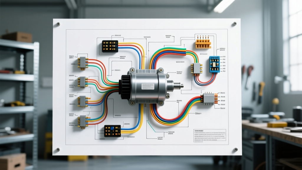
Understanding the Automotive Magnetic Starter Circuit
In heavy-duty automotive, agricultural, and classic V8 applications, the starter motor requires hundreds of amps to crank the engine. Routing this current directly through the ignition switch would instantly melt the steering column wiring. This is where the magnetic starter switch (commonly referred to as a starter solenoid or heavy-duty relay) becomes critical. The magnetic starter wiring diagram dictates how a low-amperage control circuit energizes an electromagnetic coil, which in turn pulls a heavy copper contact disc to bridge the high-amperage load circuit. When a vehicle experiences a no-crank condition, the failure is frequently isolated to this exact component or its surrounding wiring.
This guide provides a comprehensive, step-by-step troubleshooting flow for diagnosing 12V and 24V magnetic starter circuits. We will cover terminal identification, coil resistance testing, voltage drop analysis under load, and mechanical contact inspection, referencing standard SAE J1284 heavy-duty starting system parameters.
Magnetic Starter Wiring Diagram: Terminal Identification
Before initiating the diagnostic flow, you must accurately identify the terminals on the magnetic starter switch. The standard 4-terminal configuration (common on Ford, International Harvester, and Class 8 truck applications) utilizes the following layout:
- BAT (B) Terminal: The primary power input. Connects directly to the battery positive post via a 1/0 AWG or 2/0 AWG stranded copper cable. This terminal is hot at all times.
- MTR (M) Terminal: The load output. Connects to the starter motor's main terminal via a 1/0 AWG or 2/0 AWG cable. It is only energized when the magnetic contacts close.
- S (Start) Terminal: The primary control input. Receives 12V/24V from the ignition switch's 'crank' position. Typically wired with 10 AWG or 12 AWG wire (often Yellow or Red with a Blue stripe).
- I (Ignition) Terminal: The ballast bypass output. Provides full battery voltage to the ignition coil during cranking only. Typically wired with 12 AWG wire (often Red with a Light Green stripe).
Note: Torque specifications for the heavy 3/8-16 UNC terminal nuts on the B and M posts are critical. Under-torquing causes high resistance and heat; over-torquing strips the copper stud. Target torque is 25-30 ft-lbs (34-40 Nm). The smaller 10-32 control terminals require 35-50 in-lbs (4-5.6 Nm).
Step-by-Step Troubleshooting Flow
Follow this sequential diagnostic tree to isolate the root cause of your starting system failure. You will need a Digital Multimeter (DMM), a remote starter switch, and a set of heavy-duty insulated jumper cables.
Phase 1: Control Circuit Verification (The Coil)
The most common cause of a 'single click, no crank' issue is a failure in the control circuit or an open magnetic coil.
- Verify Control Voltage: Set your DMM to DC Volts. Place the black probe on a clean chassis ground and the red probe on the S terminal. Have an assistant turn the key to the 'Start' position. You should read within 0.5V of battery voltage (e.g., 12.1V on a 12.6V system). If voltage is low, trace the 12 AWG control wire back through the neutral safety switch and ignition switch.
- Test Coil Resistance (Bench Test): If the switch is removed, set the DMM to Ohms. Measure across the S terminal and the switch's metal mounting base (ground). A healthy 12V magnetic coil typically reads between 0.4 and 1.2 ohms. A reading of infinite resistance (OL) indicates a broken internal winding. A reading near zero indicates a shorted coil.
- Verify Ground Path: Many automotive magnetic starters ground through the metal mounting bracket to the engine block or fender well. If the mounting surface is painted, rusted, or corroded, the coil will not energize. Scrape the mating surface to bare metal and re-test.
Phase 2: Load Circuit & Contact Inspection (Terminals B & M)
If the control circuit is verified and the solenoid audibly 'clunks' but the starter does not spin, the internal heavy contacts are likely compromised.
- The Jumper Test: With the transmission in Park/Neutral and the ignition OFF, use a heavy-duty insulated screwdriver or jumper cable to briefly bridge the BAT and MTR terminals directly. Warning: Expect heavy sparking. If the starter spins vigorously, the starter motor and its ground are functional, confirming the fault lies inside the magnetic switch's internal contact disc.
- Internal Contact Degradation: Over thousands of cranking cycles, the copper contact disc and the stationary brass terminals suffer from electrical arcing. This creates a layer of copper oxide, which is a poor conductor. This results in severe voltage drop across the switch, starving the starter motor of amperage.
Phase 3: Voltage Drop Testing Under Load
Voltage drop testing is the definitive method for evaluating the health of the magnetic starter wiring diagram under real-world cranking loads. According to Delco Remy heavy-duty starting system guidelines, the maximum allowable voltage drop across the entire positive cranking circuit is 0.5V, with no single connection exceeding 0.1V.
- Set the DMM to DC Volts.
- Place the red probe directly on the battery positive post (not the clamp).
- Place the black probe on the starter motor's main input terminal (past the magnetic switch).
- Crank the engine for 5 seconds. A healthy system will show a drop of 0.3V to 0.4V. If the reading exceeds 0.6V, you have excessive resistance in the 1/0 AWG cables, the terminal crimps, or the internal magnetic contacts.
Symptom-Cause-Fix Decision Tree
| Symptom | Measured Value / Observation | Probable Cause | Corrective Action |
|---|---|---|---|
| No sound, no crank | 0V at S terminal during crank | Open control circuit, faulty ignition switch, or tripped neutral safety switch. | Trace 12 AWG control wire; bypass safety switch temporarily to verify. |
| Single loud click, no crank | 12V at S terminal; 12V at BAT; 0V at MTR | Magnetic coil energized, but internal heavy contacts are welded open or severely pitted. | Replace magnetic starter switch. Do not attempt to rebuild sealed units. |
| Rapid clicking (machine gun) | System voltage drops below 9.5V during crank attempt | Weak battery, loose battery cable clamps, or undersized control wire causing coil dropout. | Load test battery; clean and torque cable clamps to 12 ft-lbs. |
| Starter spins, engine doesn't turn | 12V at MTR; Starter solenoid (on motor) fails to engage Bendix drive | Starter motor's secondary throw-out solenoid failure or damaged flywheel ring gear. | Inspect flywheel teeth; replace starter motor assembly. |
| Starter remains engaged after key release | 12V present at MTR with key in 'Run' or 'Off' | Internal magnetic contact disc has welded to the stationary terminals due to extreme arcing. | Immediately disconnect battery. Replace switch and inspect starter motor for overspin damage. |
Real-World Failure Modes and Wire Degradation
When analyzing a magnetic starter wiring diagram in the field, technicians must look beyond the switch itself. Environmental and thermal factors heavily influence system longevity.
Thermal Runaway in Control Wiring: The magnetic coil requires a massive 'pull-in' current (often 30 to 45 amps for a fraction of a second) to overcome the spring tension and close the heavy contacts, followed by a lower 'hold-in' current (10 to 15 amps). If the operator holds the key in the crank position for more than 15 seconds, or if the ignition switch fails to return to the 'run' position, the 12 AWG S-terminal wire will overheat. The insulation will melt, potentially shorting against the chassis and causing an under-hood fire. Always verify that the ignition switch return spring is functioning correctly.
Galvanic Corrosion at Bi-Metal Junctions: The heavy 1/0 AWG cables often feature copper lugs bolted to brass or steel studs on the magnetic switch. In marine or heavy winter-salt environments, galvanic corrosion creates a high-resistance barrier. This manifests as a voltage drop that mimics a dead battery. Applying a dielectric grease (such as Pico Automotive approved battery terminal protector) over the assembled and torqued terminals is mandatory to prevent moisture ingress and subsequent copper oxide formation.
Parasitic Draw from Welded Contacts: A subtle but destructive failure mode occurs when the internal contact disc becomes slightly welded to one of the heavy terminals. This may not be enough to keep the starter motor spinning, but it will maintain a continuous electrical bridge between the battery and the starter motor's internal brushes. This results in a massive parasitic draw that will drain a 100Ah battery overnight and can cause the starter motor to overheat and smolder. If a vehicle exhibits unexplained battery drain, perform a voltage drop test across the B and M terminals with the vehicle off; any reading above 0.00V indicates a welded magnetic contact.
Reference Specifications and Sources
- SAE International: SAE J1171 (External Ignition Protection for Marine Electrical Devices) and SAE J1284 (Heavy Duty Starting System Performance Standards) provide the baseline for voltage drop limits and environmental sealing requirements for magnetic switches.
- Delco Remy / BorgWarner: Heavy-Duty Starting and Charging Systems Service Manuals outline the specific pull-in/hold-in amperage curves for 12V and 24V commercial vehicle magnetic solenoids.
- Wire Gauge Standards: SAE J1128 dictates the thermal and physical properties of automotive primary wire, confirming the necessity of 1/0 AWG for loads exceeding 150A and 12 AWG for control circuits.