Integrating High-Draw Wellness Amenities in Expedition Vehicles
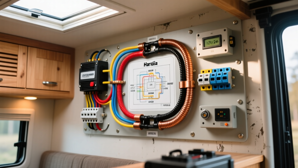
Upgrading a luxury Class B RV, expedition trailer, or custom Sprinter van with a wellness module represents the pinnacle of overland modification. However, integrating a high-draw resistive load like a Finnish sauna heater into a mobile DC-to-AC electrical system requires meticulous planning. Unlike standard automotive accessories, a sauna heater demands sustained, high-amperage alternating current (AC) that can quickly overwhelm undersized inverters, trigger Battery Management System (BMS) shutdowns, or cause catastrophic voltage drops. Referencing a comprehensive harvia sauna heater wiring diagram adapted for mobile and marine environments is critical to ensure safety, efficiency, and compliance with recreational vehicle electrical standards.
This guide details the complete electrical architecture required to install a Harvia Compact or KIP series heater (typically 2.3kW to 6.0kW) into an off-grid vehicle platform. We will cover split-phase inverter configurations, marine-grade wire sizing, heavy-duty contactor pinouts, and vibration-resistant termination methods required for off-road expedition vehicles.
System Architecture: Power Flow and Transfer Logic
In a stationary home, a Harvia heater connects directly to a 240V or 120V dedicated breaker. In an expedition vehicle, the power flow is vastly more complex. The system must bridge a 12V or 48V Lithium Iron Phosphate (LiFePO4) battery bank, a high-capacity inverter/charger, and an automatic transfer switch (ATS) that seamlessly transitions between shore power, an onboard generator, and battery inversion.
For a 3kW Harvia heater operating at 240V, the continuous AC draw is approximately 12.5 Amps per leg. While this seems manageable, the DC-side draw on a 12V system would exceed 250 Amps—well beyond the continuous rating of most standard automotive alternators and basic BMS units. Therefore, high-end RV modifications mandate a 48V DC architecture or a 120V/240V split-phase inverter stack (such as dual Victron MultiPlus-II units or a Quattro with an autotransformer) to keep DC currents below 100 Amps and utilize standard AC branch circuit wiring.
Core Electrical Requirements for Mobile Sauna Installs
- Wire Type: Solid-core residential Romex is strictly prohibited in mobile applications due to vibration-induced work-hardening and fracture. You must use stranded, tinned marine copper (e.g., THHN/THWN-2 or UL 1426 boat cable).
- Terminations: All lugs must be crimped using a hydraulic press and sealed with dual-wall adhesive heat shrink to prevent moisture ingress and corrosion.
- Vibration Mitigation: All AC and DC busbars, contactors, and breakers must be mounted on DIN rails or reinforced composite backing plates, utilizing nylon-insert lock nuts and medium-strength threadlocker (Loctite 243).
- Overcurrent Protection: A Class T fuse is mandatory on the main DC positive trunk, while a double-pole GFCI breaker is required on the AC branch circuit feeding the sauna.
Component Sizing & Wire Gauge Specifications
The following table outlines the minimum AWG requirements for a 3kW (240V split-phase) or 3kW (120V single-phase) Harvia installation in a vehicle environment, adhering to ABYC E-11 AC & DC Electrical Systems on Boats standards, which serve as the gold standard for high-end, off-road RV builds.
| Circuit Segment | Voltage / Phase | Max Continuous Amps | Required Wire Gauge (AWG) | Overcurrent Protection |
|---|---|---|---|---|
| Battery Bank to DC Busbar | 48V DC | 120A | 2/0 AWG Tinned Copper | 150A Class T Fuse |
| DC Busbar to Inverter Stack | 48V DC | 100A | 1/0 AWG Tinned Copper | 125A ANL Fuse |
| Inverter AC Out to Sub-Panel | 120V/240V Split | 50A (Total) | 6 AWG Stranded THHN | 50A Double-Pole Breaker |
| Sub-Panel to Harvia Heater | 240V (L1, L2, N, PE) | 12.5A per leg | 12 AWG Stranded (4-conductor) | 20A Double-Pole GFCI |
| Harvia Control Circuit (Thermostat) | 240V AC Control | < 1A | 18 AWG Stranded | Inline 2A Glass Fuse |
Harvia Sauna Heater Wiring Diagram: Component Mapping
When adapting the standard Harvia wiring schematic for an RV, the primary modification involves the external contactor and thermal management relays. In a residential home, the heater connects to a simple wall switch. In a vehicle, we integrate the heater's control circuit with the RV's smart monitoring system (e.g., Victron Cerbo GX) to automatically shed the sauna load if the battery State of Charge (SoC) drops below 20% or if the inverter temperature exceeds safe thresholds.
Contactor and Control Panel Pinout
Harvia units utilize a heavy-duty internal or external contactor to switch the massive resistive load of the heating elements. Below is the terminal mapping for integrating the Harvia control board with a DIN-mounted Schneider Electric iCT 25A contactor and an external overheat protector.
| Terminal / Pin | Wire Color (Mobile Standard) | Connection Destination | Function |
|---|---|---|---|
| L1, L2 (Main Power) | Black, Red (AC Lines) | Double-Pole GFCI Breaker | 240V AC Main Power Input |
| N (Neutral) | White (AC Neutral) | Neutral Busbar | Control Circuit Return Path |
| PE (Ground) | Green/Yellow (AC Ground) | Chassis / Ground Busbar | Safety Earth Ground (Critical for GFCI) |
| Contactor Coil (A1) | Blue (Control Line) | Thermostat / Smart Relay | Energizes contactor to heat elements |
| Contactor Coil (A2) | White (Control Neutral) | Neutral Busbar | Completes control circuit |
| Overheat Protector (ST) | Orange (Sensor Wire) | Harvia Internal Capillary Tube | Cuts coil power if enclosure exceeds 110°C |
Step-by-Step Mobile Installation Procedure
- Mount the Inverter and Autotransformer: Secure the Victron MultiPlus-II and autotransformer to a reinforced aluminum extrusion frame. Ensure a minimum of 4 inches of clearance on all sides for active cooling fans. Connect the 48V DC input using 1/0 AWG wire and crimped 3/8" ring terminals.
- Install the AC Sub-Panel: Mount a marine-grade, splash-proof AC distribution panel. Install the 20A double-pole GFCI breaker dedicated solely to the Harvia heater. Note: GFCI protection is mandatory per NFPA 1192 Standard on Recreational Vehicles for any amenity involving water or high humidity.
- Route the AC Branch Circuit: Run a 4-conductor, 12 AWG marine cable from the GFCI breaker to the Harvia junction box. Keep AC wiring separated from DC wiring by at least 6 inches to prevent electromagnetic interference (EMI) with the RV's CAN bus and sensor networks.
- Terminate the Harvia Block: Strip the wires and apply ferrule crimps to the stranded ends before inserting them into the Harvia screw-terminal block. This prevents individual copper strands from fraying and causing short circuits under heavy off-road vibration.
- Integrate Smart Load Shedding: Wire the Harvia's control circuit through a Victron Smart BatteryProtect or a programmable relay connected to the Cerbo GX. Configure the relay to open (cutting power to the contactor coil A1) if the DC bus voltage drops below 46.0V, preventing catastrophic LiFePO4 cell depletion.
Troubleshooting Common Mobile Sauna Electrical Faults
Operating high-wattage resistive heaters in a mobile environment introduces unique failure modes not found in residential wiring. Use this diagnostic matrix to resolve common issues:
- Symptom: Contactor rapidly clicks (chatters) but elements do not heat.
Cause: Severe AC voltage drop at the inverter output due to undersized wiring or loose neutral busbar connections.
Fix: Verify 12 AWG wire integrity. Check the neutral-to-ground bond at the inverter (ensure it is only bonded at the source, not the sub-panel). Torque all busbar lugs to manufacturer specs (typically 4-5 Nm). - Symptom: Inverter shuts down with "High Temperature" alarm after 10 minutes of sauna operation.
Cause: Inadequate ventilation in the RV's electrical closet, combined with the continuous 3kW load generating massive heat in the inverter's MOSFETs.
Fix: Install active 12V DC exhaust fans in the electrical bay, thermostatically controlled to activate at 35°C. Ensure the inverter's internal fans are free of dust and lint. - Symptom: GFCI breaker trips immediately upon energizing the heater.
Cause: Moisture ingress in the exterior junction box, or a floating ground on the inverter autotransformer setup.
Fix: Inspect all exterior wire glands and apply dielectric grease. Verify that the autotransformer's center-tap neutral is solidly bonded to the RV chassis ground via the appropriate gauge wire (minimum 6 AWG).
Authoritative References
For further engineering data on mobile electrical systems and high-draw appliance integration, consult the following resources:
- Victron Energy: Wiring Unlimited Guide - Comprehensive reference for DC busbar sizing, split-phase inverter stacking, and mobile grounding topologies.
- NFPA 1192: Standard on Recreational Vehicles - Mandates for GFCI protection, wire routing, and thermal clearances in RV modifications.
- ABYC E-11: AC & DC Electrical Systems on Boats - The definitive standard for vibration-resistant, tinned copper wiring and overcurrent protection in harsh, mobile environments.