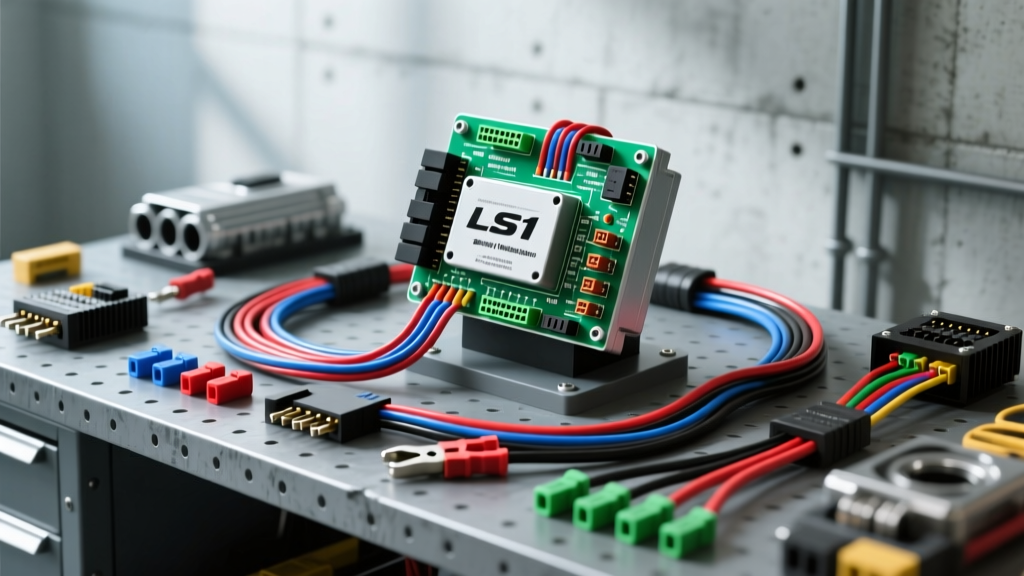
Decoding Factory Car Wiring Schematics for ECU Swaps
Executing a standalone ECU upgrade—whether dropping a GM LS1 into a classic chassis or upgrading a modern platform to a Holley Terminator X or MegaSquirt system—requires more than just connecting plugs. The foundation of a reliable, noise-free installation lies in your ability to accurately read and interpret OEM car wiring schematics. Factory service manuals contain the exact electrical topology, wire color codes, and splice locations necessary to integrate aftermarket engine management without triggering parasitic draws, ground loops, or sensor failures.
When analyzing manufacturer diagrams, it is critical to understand the nomenclature used for circuit identification. For instance, in General Motors schematics, splices are designated with an 'S' prefix (e.g., S101), while physical chassis grounds use a 'G' prefix (e.g., G102). Misinterpreting a shared schematic ground node as a physical single-point ground is a common failure mode that leads to severe electromagnetic interference (EMI) in sensitive 5V reference circuits. According to the GM Service Information guidelines published by Helm Inc., a single ground node symbol on a schematic may actually represent a distributed grounding harness spanning multiple physical eyelets bolted to the cylinder head and chassis.
The LS1 80-Pin ECU Connector Breakdown
The GM Gen III LS1 utilizes an 80-pin ECU configuration divided across three distinct connectors: Black, Blue, and Red. When adapting factory car wiring schematics to an aftermarket standalone harness, you must isolate the critical power, ground, and sensor circuits while safely terminating unused OEM modules (like the BCM or VATS). Below is a reference table for the most critical pins required for a basic running-and-driving standalone configuration.
| Connector | Pin Number | Wire Color | Circuit Function | AWG & Wire Type |
|---|---|---|---|---|
| Black | 1 | Pink | Ignition 12V (Switched) | 14 AWG TXL |
| Black | 2 | Pink | Ignition 12V (Switched) | 14 AWG TXL |
| Black | 3 | Orange | Battery 12V (Constant) | 12 AWG TXL |
| Black | 80 | Black/White | ECU Main Power Ground | 10 AWG TXL |
| Blue | 48 | Light Green | Crankshaft Sensor Signal | 18 AWG Shielded |
| Blue | 49 | Purple | Crankshaft Sensor Low Ref | 18 AWG Shielded |
| Red | 21 | Dark Green | Tachometer Output Signal | 18 AWG TXL |
| Red | 70 | Dark Blue | Fuel Pump Relay Control | 16 AWG TXL |
Wire Type and Insulation Standards
When fabricating or modifying your harness based on these car wiring schematics, never use standard PVC-insulated wire. Under-hood temperatures routinely exceed 125°C (257°F), which will melt PVC and cause catastrophic short circuits. Always specify SAE J1128 compliant TXL (Cross-linked polyethylene) or GXL wire, which features high-temperature resistance and a thin wall for reduced harness bulk. You can verify these material specifications directly through the SAE J1128 Low Tension Primary Cable standard.
Translating OEM Schematics to Aftermarket Sensor Circuits
Sensor wiring is where the majority of standalone ECU driveability issues originate. Factory schematics detail the 5-Volt Reference (5VREF), Signal, and Low-Reference (Sensor Ground) circuits for the Throttle Position Sensor (TPS), Manifold Absolute Pressure (MAP), and Intake Air Temperature (IAT) sensors.
The 5V Reference and Low-Reference Topology
In GM car wiring schematics, the 5VREF circuit (typically a Gray wire) is shared among multiple sensors. When integrating an aftermarket ECU, it is highly recommended to isolate the 5VREF circuits. Run a dedicated 18 AWG 5VREF wire from the ECU to the TPS, and a separate 18 AWG wire to the MAP sensor. This prevents a short in the TPS harness from pulling down the MAP sensor reference voltage, which would cause severe fueling miscalculations.
Similarly, the Low-Reference circuit (typically Black or Purple/White) must be wired back to the ECU's dedicated analog-to-digital (A/D) ground pins. Do not ground the sensor's low-reference wire to the engine block. The ECU measures the voltage drop across the sensor; introducing chassis ground noise into the low-reference return path will manifest as erratic idle and false knock sensor readings.
VR Sensor Shielding and Air Gaps
The Crankshaft Position Sensor (CKP) and Camshaft Position Sensor (CMP) on the LS1 are Variable Reluctance (VR) sensors. The car wiring schematics show these as a twisted pair of wires (Light Green and Purple for the CKP). When extending or repairing these circuits, you must use shielded twisted-pair cable. The shield drain wire must be grounded only at the ECU end to prevent ground loops. Furthermore, ensure the physical air gap between the VR sensor tip and the reluctor wheel is maintained between 0.020' and 0.045' to guarantee a clean sine wave signal above 4,000 RPM.
High-Current Modifications: Fuel Pump and Injector Circuits
Upgrading to high-impedance or low-impedance injectors, alongside high-flow fuel pumps like the Walbro 450 or DeatschTek DW400, requires a thorough understanding of the high-current sections of the car wiring schematics. Factory wiring is often marginal for modern E85 flex-fuel upgrades, necessitating thicker gauge wiring and upgraded relay topologies.
Relay Integration and AWG Sizing
The factory ECU ground-switches the fuel pump relay (Pin 70, Dark Blue). When upgrading the fuel system, do not run the fuel pump's primary power through the factory harness. Instead, use the ECU's fuel pump output to trigger a secondary, high-amperage Bosch-style 30/40A relay mounted near the fuel tank.
| Circuit | Recommended AWG | Connector Terminal Type | Crimping Standard |
|---|---|---|---|
| Main ECU Power & Ground | 10 AWG TXL | Metri-Pack 280 Series | Delphi Hand Crimper / Ratcheting |
| Injector Power Feed | 12 AWG TXL | Metri-Pack 280 Series | Delphi Hand Crimper / Ratcheting |
| Injector ECU Ground | 14 AWG TXL | Metri-Pack 150 Series | Delphi Hand Crimper / Ratcheting |
| Fuel Pump Primary Power | 8 AWG TXL | Weather-Pack / Ring Terminal | Hex-Crimp or Ratcheting |
| Sensor Signals (TPS, MAP) | 18 AWG TXL | Metri-Pack 150 Series | Delphi Hand Crimper / Ratcheting |
Flyback Diodes and Inductive Kickback
When modifying the schematics to include aftermarket relays for the fuel pump, cooling fans, or A/C compressor, you must account for inductive kickback. When the ECU's internal driver opens the circuit to a relay coil, the collapsing magnetic field generates a high-voltage spike that can fry the ECU's internal transistors. Always install a 1N4001 flyback diode across the relay coil terminals (cathode to 12V, anode to the ECU switched ground) to safely dissipate this voltage spike.
CAN-Bus Networking and Termination
Modern standalone ECUs and digital dashes rely on Controller Area Network (CAN-bus) protocols to share data. Factory car wiring schematics depict CAN-High and CAN-Low as a twisted pair, typically colored Dark Green and Light Green (or similar variations depending on the OEM). When integrating a digital dash (like a Holley EFI 7-inch monitor), you must wire the CAN-H and CAN-L wires directly to the ECU using a twisted pair with a minimum of 3 twists per inch.
Critical to this modification is the termination resistance. A properly functioning CAN-bus requires exactly 120 ohms of resistance across the network. Most aftermarket ECUs and dashes feature internal 120-ohm terminating resistors. If your schematic shows multiple modules on the bus, ensure that only the two devices at the physical ends of the network have their termination resistors enabled. A multimeter reading of 60 ohms across the CAN-H and CAN-L pins at the OBD2 diagnostic port confirms proper dual-termination, while a reading of 120 ohms indicates a missing terminator, leading to dropped packets and erratic gauge readings.
Common Schematic Misinterpretations and Failure Modes
Even seasoned builders fall victim to specific pitfalls when relying solely on visual interpretations of car wiring schematics without understanding the physical harness routing.
- The 'Shared Ground' Illusion: Schematics often show multiple sensors grounding to a single node (e.g., G102). In reality, G102 might consist of three separate ring terminals bolted to the rear of the passenger side cylinder head. If you only secure one ring terminal and leave the others ungrounded during a harness tuck, the EGR and EVAP solenoids may lose their ground path, triggering phantom Check Engine Lights.
- PWM vs. Static Fuel Pump Control: Later model schematics (2004+ GM trucks) utilize a Fuel Pump Control Module (FPCM) that modulates the fuel pump via a Pulse Width Modulated (PWM) signal rather than a simple 12V relay. Swapping an older LS1 engine into a newer chassis requires bypassing the factory PWM module and wiring a standard 12V relay, otherwise the pump will only receive 5V-7V at idle and starve the engine under load.
- Ignition Coil Dwell Wiring: The LS1 uses an Ignition Control Module (ICM) wired directly to the coils. When upgrading to LS2-style coil-near-plug (CNP) setups, the car wiring schematics must be modified to supply a dedicated 12V switched feed to each coil's 'A' pin, while the ECU provides the ground-trigger on the 'B' pin. Relying on the factory ICM harness for CNP coils will result in weak spark and misfires above 5,500 RPM.
Final Verification and Continuity Testing
Before applying battery power to your newly fabricated or modified standalone harness, perform a rigorous continuity test. Using a digital multimeter, verify that all primary ground circuits (10 AWG and 12 AWG) show less than 0.2 ohms of resistance to the engine block and chassis. Consult the Holley Technical Library for specific ECU pinout sheets to cross-reference your modified harness against the manufacturer's baseline. Mastering the translation of factory car wiring schematics into a purpose-built standalone harness is the ultimate safeguard against electrical gremlins, ensuring your engine management system performs flawlessly on the street and the track.