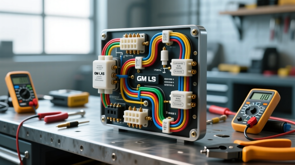
The Financial Impact of Ignition Wiring Misdiagnosis
When diagnosing a cylinder misfire, the instinct for many DIY mechanics and general repair shops is to immediately replace the ignition coil and spark plug. However, a deep analysis of the ignition coil wiring diagram often reveals that the root cause lies in the harness, connector terminals, or Powertrain Control Module (PCM) driver circuit. Misinterpreting the wiring schematic or using improper diagnostic tools can escalate a simple $25 pigtail repair into a catastrophic $1,500 PCM replacement. This guide breaks down the true costs, required diagnostic tooling, and precise wiring specifications for modern Coil-On-Plug (COP) systems, using the ubiquitous GM 5.3L LS V8 (2007-2013) as our primary case study.
Cost Breakdown: Parts vs. Diagnostics
Understanding the financial stakes requires comparing the cost of shotgun parts replacement against targeted electrical diagnostics. Below is a real-world cost analysis for a single-cylinder misfire (e.g., P0301) on a GM 5.3L Vortec engine.
| Repair / Diagnostic Path | Estimated Parts Cost | Labor / Time | Risk Factor |
|---|---|---|---|
| Replace All 8 OEM Coils (Shotgun) | $480 - $640 | 2.5 Hours | High (Does not fix wiring faults) |
| Replace Single Aftermarket Coil | $35 - $60 | 0.5 Hours | Medium (High failure rate on cheap coils) |
| Pigtail Harness Repair (Correct Diag) | $18 - $28 | 1.0 Hour | Low (Permanent OEM-style fix) |
| PCM Replacement (Due to Tool Damage) | $800 - $1,200 | 2.0 Hours + Flash | Critical (Caused by improper testing) |
Required Diagnostic Tools (And What to Avoid)
The most critical aspect of interpreting an ignition coil wiring diagram is knowing how to test the circuits without destroying the PCM. The PCM trigger circuit (often labeled as IC Control or IGT) is a low-current logic signal. The PCM uses a low-side driver transistor to ground the coil's primary winding, typically handling less than 0.5 amps.
The Danger of Standard Test Lights
Using a standard incandescent test light to probe the PCM trigger wire is a catastrophic mistake. A standard 12V test light draws between 1.5 and 2.5 amps. If you back-probe the trigger wire and command the circuit, the test light will pull excessive current through the PCM's internal driver transistor, instantly burning it out. This transforms a minor wiring issue into a mandatory PCM replacement. Always use high-impedance digital multimeters or dedicated logic probes.
Essential Tool Specification Chart
| Tool Category | Minimum Specification | Estimated Cost | Application in Ignition Diag |
|---|---|---|---|
| Digital Multimeter (DVOM) | 10 Megohm impedance, Min/Max recording | $50 - $150 | Testing 12V feed, ground continuity, and voltage drop. |
| Automotive Oscilloscope | 2-Channel, 20MHz bandwidth, 10kV ignition lead | $400 - $1,500 | Analyzing coil dwell time, kV firing line, and oscillation. |
| Logic Probe / NOID Light | High-impedance LED, specific to COP systems | $25 - $45 | Verifying PCM trigger signal presence without overloading. |
| Terminal Crimp Tool | Metri-Pack 150/280 specific ratcheting crimper | $80 - $120 | Repairing damaged pigtail harnesses to OEM standards. |
For advanced diagnostics, an oscilloscope is unparalleled. As detailed by Pico Technology's automotive training resources, capturing the secondary ignition waveform allows technicians to identify issues like carbon tracking, excessive spark plug gap, or primary circuit resistance without ever removing the coil from the engine bay.
Decoding the Ignition Coil Wiring Diagram: GM 5.3L V8 Case Study
To perform accurate repairs, you must read the manufacturer-specific ignition coil wiring diagram. The 2007-2013 GM 5.3L LS engine (LC9, LMG, LH8) utilizes a square-body Coil-On-Plug design (ACDelco part # D585 or 12573190 equivalent). The connector is a 6-way Aptiv (formerly Delphi) Metri-Pack 150/280 series housing, though only three or four pins are actively populated depending on the exact sub-model year and PCM strategy.
Pinout and Wire Gauge Specifications
When probing the harness side of the connector, reference the following OEM wire color codes and AWG (American Wire Gauge) specifications. Note that wire colors may vary slightly by specific model year and trim, but the circuit functions remain constant.
- Pin A (12V Ignition Feed): Pink wire, 16 AWG. This circuit is fed directly from the ignition relay. It must carry sufficient current to saturate the coil's primary winding. A voltage drop test here should show no more than 0.2V drop from the battery positive terminal with the key in the RUN position.
- Pin B (Low Reference / Ground): Black with White tracer, 18 AWG. This is the dedicated coil ground, usually routing to a splice pack or directly to the engine block ground stud. High resistance here causes weak spark and coil overheating.
- Pin C (PCM Trigger / IC Control): Varies by cylinder (e.g., White/Black, Yellow/Black), 20 AWG. This is the low-side trigger signal from the PCM. It operates on a 5V logic pull-up, dropping to near 0V when the PCM commands the coil to dwell.
- Pins D, E, F: Typically empty cavities in this specific LS generation, reserved for feedback circuits (IGF) on newer global architectures or different engine families.
Professional Harness Repair vs. Replacement
When the ignition coil wiring diagram confirms that the PCM and coil are functional, but the circuit is open or shorted, the harness must be repaired. The most common failure point is the pigtail connector itself. Heat cycling, engine vibration, and capillary action (where oil wicks up into the wiring loom from a leaking valve cover) cause terminal fretting corrosion and plastic housing embrittlement.
The Solder vs. Crimp Debate
Under SAE International standards for automotive electrical environments, soldering is strictly prohibited for engine bay harness repairs. Solder creates a rigid joint that is highly susceptible to fatigue cracking under the constant vibration of a running V8 engine. Furthermore, solder wicking changes the flexibility and resistance of the wire. The only acceptable repair method is using an OEM-style ratcheting crimper to attach new Metri-Pack terminals, followed by adhesive-lined heat shrink tubing to seal out moisture and dielectric grease applied to the connector cavity.
Step-by-Step Cost-Effective Repair Protocol
- Verify the Fault: Use a high-impedance DVOM to check for 12V at Pin A and continuity to ground at Pin B. Use a logic probe to verify the PCM trigger pulse at Pin C while cranking.
- Isolate the Harness: If the coil is known-good but lacks a trigger signal, back-probe Pin C. If the signal is present at the PCM connector but missing at the coil, you have an open circuit in the 20 AWG trigger wire.
- Execute the Repair: Cut the damaged pigtail 3 inches from the connector. Strip the wires, crimp on new Aptiv Metri-Pack terminals using the correct die (usually a 1.5mm or 2.8mm tab die depending on the cavity), and insert them into a new OEM connector housing until you hear the tactile click.
- Seal and Protect: Apply marine-grade adhesive heat shrink over the splices. Coat the male coil terminals with a light layer of dielectric tune-up grease to prevent future micro-arcing and corrosion.
Conclusion and Authoritative References
Mastering the ignition coil wiring diagram is not just about fixing a misfire; it is about protecting expensive electronic modules and performing repairs that withstand the harsh under-hood environment. By investing in the correct high-impedance diagnostic tools and adhering to OEM crimping standards, technicians and advanced DIYers can save hundreds of dollars in misdiagnosed parts and labor. For further reading on proper automotive electrical repair techniques, consult the Haynes Manuals Ignition Testing Guide and always reference factory service information for your specific vehicle's pinout variations.