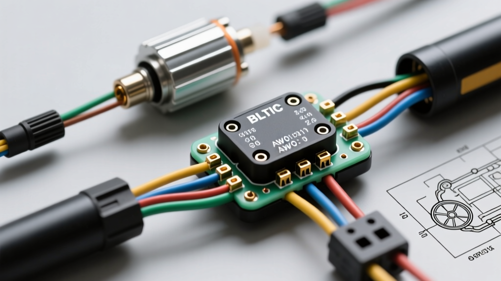
The Problem with Generic Schematics
When troubleshooting or building a custom light electric vehicle (LEV), many DIY mechanics and repair technicians start their journey by searching for an electric scooter wiring diagram pdf free download. While these generic documents can provide a basic conceptual overview, they are notoriously unreliable for modern, high-performance builds. Most freely available PDFs depict outdated brushed DC motor circuits or generic, unbranded Chinese controllers that lack specific pinout mappings, accurate AWG requirements, and waterproof connector specifications.
Modern electric scooters—ranging from commuter models like the Segway Ninebot and Xiaomi M365 to high-performance DIY builds utilizing 36V or 48V Brushless DC (BLDC) hub motors—require precise signal routing. A mismatched hall sensor phase angle or an undersized power harness can result in catastrophic controller failure, melted phase wires, or erratic throttle behavior. This technical reference replaces the need for low-resolution PDF downloads by providing exact, actionable wiring specifications, pinout tables, and diagnostic procedures for standard 36V/48V BLDC e-scooter controllers.
Main Power and Battery Harness Specifications
The main power harness connects the lithium-ion battery pack to the motor controller's primary DC bus. Due to the high continuous current draw (often 15A to 30A continuous, with peaks up to 45A), wire gauge selection and connector integrity are critical. According to the SAE J1128 Low Tension Primary Cable Standard, automotive and LEV wiring must account for thermal derating in bundled harnesses.
| Circuit | Wire Gauge (AWG) | Insulation Type | Connector Standard | Color Code |
|---|---|---|---|---|
| Battery Main V+ | 10 AWG | Silicone (200°C) | XT60 or XT90 | Red |
| Battery Main V- | 10 AWG | Silicone (200°C) | XT60 or XT90 | Black |
| Ignition / Key Switch | 18 AWG | PVC / Cross-linked | JST-SM 2-Pin | Red (Signal) |
| Charge Port V+ | 12 AWG | Silicone | 3-Pin GX12 / RCA | Red |
Never use standard PVC-insulated wire for the main battery harness. Silicone wire offers superior strand count (typically 1050 strands for 10 AWG), providing lower DC resistance and the flexibility required to absorb the high-frequency vibrations inherent to e-scooter frames. Furthermore, always incorporate an inline DC circuit breaker or high-amperage fuse (e.g., 40A ANL fuse) on the main V+ line within 6 inches of the battery positive terminal to prevent thermal runaway in the event of a controller short.
BLDC Motor Phase and Hall Sensor Mapping
The heart of the e-scooter drivetrain is the BLDC hub motor. Wiring the motor requires two distinct harnesses: the high-current phase wires and the low-voltage hall effect sensor array. Miswiring these circuits is the leading cause of blown MOSFETs in aftermarket controllers. For comprehensive BLDC theory and phase mapping, the Kelly Brushless Motor Controller Documentation serves as an excellent baseline for understanding 120-degree versus 60-degree sensor phasing.
Phase Wire Specifications
Phase wires carry the pulsed DC current that drives the motor stator. They must be sized to handle peak amperage without voltage sag.
- Gauge: 14 AWG (Minimum for 350W-500W motors) or 12 AWG (for 800W+ motors).
- Colors: Yellow (Phase A), Green (Phase B), Blue (Phase C).
- Connectors: 4.5mm or 6.0mm Bullet connectors, enclosed in heat-shrink tubing. Avoid JST connectors for phase wires, as they will melt under load.
Hall Sensor Pinout Reference
Hall sensors provide rotor position feedback to the controller. Most modern e-scooters use a 5-pin Higo waterproof connector or a 5-pin JST-SM connector. The standard color mapping is highly consistent across the industry, though the physical pin arrangement inside the plastic housing may vary.
| Pin Number | Function | Wire Color | Gauge | Voltage Level |
|---|---|---|---|---|
| 1 | Hall VCC (5V) | Red | 24 AWG | 5.0V DC |
| 2 | Hall Ground | Black | 24 AWG | 0V DC |
| 3 | Hall Signal A | Yellow | 24 AWG | 0V - 5V Square Wave |
| 4 | Hall Signal B | Green | 24 AWG | 0V - 5V Square Wave |
| 5 | Hall Signal C | Blue | 24 AWG | 0V - 5V Square Wave |
Warning: If your controller uses a generic 6-pin connector, the 6th pin is often a spare ground or a thermistor wire (typically White or Orange). Never connect the 5V Red wire to a thermistor pin, as this will instantly destroy the motor's internal temperature sensor.
Throttle, E-Brake, and Accessory Circuits
Low-voltage signal circuits dictate the logic and safety parameters of the scooter. Unlike the generic diagrams found in a random electric scooter wiring diagram pdf free download, actual OEM schematics differentiate between normally open (NO) and normally closed (NC) logic for braking and accessory circuits.
Signal Voltage Specifications
- Throttle: Uses a linear Hall-effect sensor. Requires 3 wires: 5V (Red), Ground (Black), and Signal (White or Green). The signal voltage sweeps from 0.8V (idle) to 4.2V (full throttle). If your controller expects a 1V-4V sweep and your throttle outputs 0V-5V, the controller will throw an over-voltage error code and disable the motor.
- E-Brake Cutoff: Most controllers use a 2-pin JST connector for brakes. A standard e-brake lever contains a microswitch. When pulled, it bridges the Signal pin to Ground, pulling the logic line low and cutting power to the MOSFET gates. Ensure your controller's brake logic matches your lever's switch type (Active Low vs. Active High).
- Headlights / Taillights: Typically driven by a 12V or 24V step-down converter internal to the controller. Do not wire LED lights directly to the 48V main battery bus unless they are rated for 36V-60V DC input.
Diagnostic Testing and Fault Isolation
When an e-scooter fails to engage, skip the guesswork and use a digital multimeter (DMM) to isolate the fault. Referencing established Electric Scooter Parts Wiring Diagrams, follow this diagnostic tree:
- Test the 5V Reference Rail: Set your DMM to DC Voltage. Back-probe the Red and Black wires on the throttle connector. You must read exactly 4.9V to 5.1V. If you read 0V, the controller's internal 7805 voltage regulator has failed, or there is a short in the hall sensor harness.
- Test the Hall Sensors: With the scooter elevated and the rear wheel spinning freely by hand, back-probe the Yellow, Green, and Blue hall signal wires. The voltage should oscillate between 0V and 5V as the magnets pass the stator. If one wire stays pinned at 0V or 5V, that specific hall sensor inside the hub motor is dead and the motor must be opened for repair.
- Test the Throttle Sweep: Back-probe the throttle signal wire. Slowly twist the throttle. The voltage should rise linearly from ~0.8V to ~4.2V. Any sudden drops to 0V indicate a broken potentiometer track inside the throttle housing.
Connector Crimping and Weatherproofing
The majority of e-scooter electrical failures are not caused by bad components, but by poor crimps and water ingress. Standard JST-SM connectors are not waterproof and will corrode rapidly when exposed to road spray. For any harness routed outside the main deck or battery enclosure, you must use IP67-rated Higo connectors. When crimping 24 AWG to 18 AWG signal wires, use a precision ratcheting crimper (such as the SN-28B or IWISS IWS-3220M) to ensure the wire barrel and insulation barrel are compressed to manufacturer tolerances. A poor crimp increases resistance, which generates heat and causes voltage drop, leading to erratic throttle behavior and controller resets under heavy acceleration.