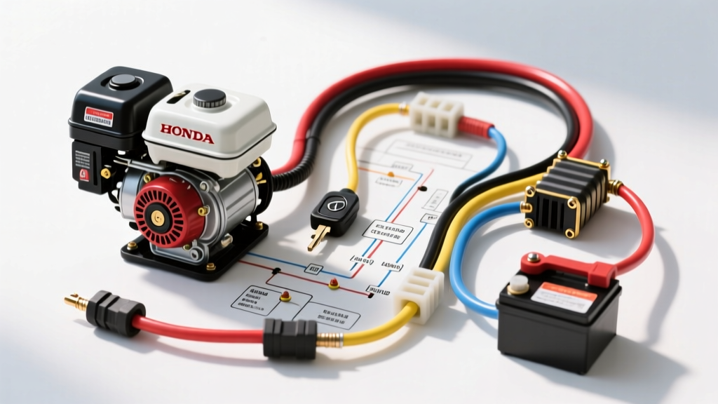
Introduction to the Honda GX390 Electric Start System
The Honda GX390 is a legendary 13HP, 389cc overhead valve (OHV) engine utilized across commercial pressure washers, industrial water pumps, heavy-duty generators, and custom off-road vehicle swaps. When equipped with the factory 12-volt electric start kit, the engine relies on a robust but straightforward DC electrical system. Understanding the official Honda GX390 electric start wiring diagram PDF is critical for technicians, equipment builders, and automotive swap enthusiasts to ensure reliable cranking, proper ignition kill functionality, and safe charging system integration.
Unlike complex automotive CAN-bus systems, the GX390 utilizes a raw, point-to-point 12V DC architecture. However, misinterpreting the schematic frequently leads to blown fuses, melted harnesses, or an engine that cranks but refuses to shut off. This comprehensive walkthrough decodes the OEM wiring diagram, detailing exact wire gauges, color codes, terminal pinouts, and torque specifications required for a flawless installation or repair.
Anatomy of the Honda GX390 Wiring Diagram PDF
When you open the OEM Honda GX390 electric start wiring diagram PDF, the schematic is divided into three primary circuits: the high-amperage starter cranking circuit, the low-amperage ignition control (kill) circuit, and the optional stator charging circuit. The system hinges on a centralized 4-post key switch that manages power distribution and magneto grounding.
Core Components and Terminal Identifiers
- Starter Motor: 12V DC, 0.9 kW output series-wound motor. Draws 80-120 Amps under peak load.
- Starter Solenoid (Relay): Heavy-duty contactor rated for 150A continuous. Features two large M8 battery/starter studs and two small 1/4" spade trigger terminals.
- Key Switch (4-Post): Manages Battery (B), Starter Trigger (S), Magneto Kill (M), and Ground (G).
- Ignition Coil (Magneto): Generates high-voltage spark; features a primary kill tab that must be grounded to halt combustion.
Step-by-Step Wiring Walkthrough
1. Battery and Main Power Feed
The foundation of the GX390 electric start system is the main power feed from the 12V battery to the starter solenoid. According to SAE International J1128 standards for low-tension primary cables, high-draw starter circuits require heavy-gauge copper to prevent catastrophic voltage drop.
Run a 4 AWG pure copper cable from the positive battery terminal to the large input stud on the starter solenoid. Secure the connection using a 3/8" ring terminal, crimped with a hydraulic or heavy mechanical crimper, and apply dielectric grease before tightening the M8 nut to 5 lbf-ft (6.8 N·m). Do not use copper-clad aluminum (CCA) wire, as the high resistance will cause the solenoid to chatter and fail to engage the starter Bendix gear.
2. Starter Motor and Solenoid Circuit
From the output stud of the solenoid, run another 4 AWG cable directly to the starter motor's main terminal. The starter motor is mounted to the engine block using two M8 x 1.25 flange bolts. Honda specifies torquing these mounting bolts to 17 lbf-ft (23 N·m) to ensure the starter pinion gear aligns perfectly with the flywheel ring gear. Improper torque can lead to stripped flywheel teeth or a grinding noise during cranking.
The starter motor casing grounds directly through the engine block. Ensure the engine block mating surface is bare metal, free of paint or rust, to provide a zero-resistance ground path back to the battery's negative terminal.
3. Ignition Kill Switch and Magneto Ground
The most misunderstood circuit in the Honda GX390 wiring diagram PDF is the ignition kill circuit. The GX390 uses a magneto ignition system, meaning it generates its own spark independently of the 12V battery. To stop the engine, the primary winding of the ignition coil must be shorted to ground.
The OEM key switch utilizes an "M" (Magneto) terminal and a "G" (Ground) terminal. When the key is turned to the OFF position, the switch internally bridges the M and G terminals, grounding the ignition coil and killing the spark. A 16 AWG green wire typically runs from the "M" terminal on the key switch to the spade connector on the ignition coil. If this wire is severed, disconnected, or suffering from high resistance, the engine will continue to run even after the key is removed (dieseling).
Wire Gauge (AWG) and Color Code Specifications
Adhering to the correct wire gauge and OEM color codes is vital for future troubleshooting and maintaining the integrity of the harness. Below is the definitive specification chart derived from the Honda Power Equipment service manuals.
| Circuit Function | OEM Wire Color | Min. AWG Size | Terminal Type | System Voltage / Current |
|---|---|---|---|---|
| Battery to Solenoid (+) | Red | 4 AWG | 3/8" Ring Terminal | 12V DC / 120A Peak |
| Solenoid to Starter (+) | Red | 4 AWG | 5/16" Ring Terminal | 12V DC / 120A Peak |
| Key Switch to Battery (+) | Red | 14 AWG | 1/4" Spade (Terminal B) | 12V DC / 5A Max |
| Key Switch to Solenoid Trigger | Yellow | 16 AWG | 1/4" Spade (Terminal S) | 12V DC / 2A Pull |
| Key Switch to Ignition Coil | Green | 16 AWG | 1/4" Spade (Terminal M) | Magneto Pulse / Ground |
| Key Switch to Chassis Ground | Black | 14 AWG | 1/4" Spade (Terminal G) | Ground Path |
Charging Coil Integration (Optional 15A/18A Kit)
Many GX390 applications, such as commercial floor buffers and mobile lighting towers, require a charging coil to maintain the 12V battery. The Honda GX390 wiring diagram PDF for the charging kit introduces a stator coil mounted under the flywheel and a rectifier/regulator module.
The stator outputs alternating current (AC). The OEM rectifier converts this to direct current (DC) and regulates the voltage to a safe 13.8V - 14.2V to prevent battery overcharging. The rectifier typically features two AC input wires (usually white or yellow) connecting to the stator, and a DC output (Red) that ties into the main battery positive feed, alongside a Black ground wire that must be bolted directly to the engine block. When installing the charging kit, ensure the flywheel is torqued to 40 lbf-ft (54 N·m) using a flywheel holder to prevent shearing the crankshaft keyway.
Troubleshooting Common Electric Start Failures
Even with a perfect wiring diagram, environmental factors and vibration can cause electrical faults. Use this decision tree to diagnose common GX390 starting issues:
Symptom: Solenoid Clicks, But Starter Does Not Turn
- Cause 1: Severe voltage drop across the main cables. Fix: Perform a voltage drop test across the 4 AWG cables while cranking. A drop greater than 0.2V indicates corrosion or an undersized wire. Replace terminals and re-crimp.
- Cause 2: Worn starter motor brushes. Fix: Disassemble the starter motor housing and measure the brush length. If brushes are worn below 0.31 inches (8mm), replace the brush plate assembly.
Symptom: Engine Starts, But Will Not Shut Off With Key
- Cause 1: Broken green kill wire or faulty key switch internal contacts. Fix: Use a multimeter set to continuity. Probe the "M" and "G" terminals on the back of the key switch while in the OFF position. If there is no continuity, the switch is defective. If the switch tests good, check the green wire for continuity from the switch to the ignition coil spade.
- Cause 2: Ignition coil kill tab shorting to debris. Fix: Clean the area around the ignition coil primary tab. Ensure the wire boot is fully seated and sealed with dielectric grease to prevent moisture ingress, which can cause intermittent grounding failures.
Symptom: Starter Spins, But Does Not Engage Flywheel
- Cause: Sticky Bendix drive or weak solenoid throw. Fix: Remove the starter. Inspect the spiral splines on the Bendix drive. Clean with electrical contact cleaner and apply a very light coat of dry graphite lubricant. Never use wet grease or WD-40, as it will attract dirt and bind the clutch mechanism.
Authoritative References
For further technical validation, always cross-reference your physical harness with the latest OEM documentation and industry standards:
- Honda Power Equipment Official Service Manuals - Provides the definitive GX series wiring schematics and torque specifications.
- SAE International J1128 Standard - Guidelines for low-tension primary cable selection and voltage drop tolerances in automotive and small engine applications.
- NGK Spark Plug Technical Bulletins - Essential reading on magneto ignition system diagnostics and proper ignition coil grounding techniques.