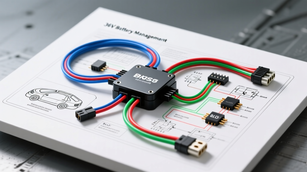
Introduction to the Jetson Bolt Electrical Architecture
When diagnosing electrical faults, upgrading components, or replacing a damaged harness on the Swagtron Jetson Bolt, locating an accurate jetson bolt wiring diagram pdf is the critical first step. Unlike traditional internal combustion vehicles, the Jetson Bolt operates as a Light Electric Vehicle (LEV) utilizing a 36V nominal lithium-ion battery pack, a Battery Management System (BMS), and a Brushless DC (BLDC) motor controller. Because factory service manuals for LEVs are rarely distributed to consumers, understanding the underlying schematic requires a deep dive into standard PEV (Personal Electric Vehicle) wiring topologies.
This advanced technical guide reconstructs the essential data typically found in the OEM jetson bolt wiring diagram pdf. We will cover the 36V BMS pin configurations, the BLDC motor controller harness, Higo waterproof connector pinouts, and precise multimeter diagnostics for hall sensor and throttle signal faults. Whether you are troubleshooting a no-start condition, a motor stutter under load, or a parasitic battery drain, this schematic breakdown provides the exact wire color codes, AWG specifications, and voltage parameters required for professional-level repair.
Decoding the 36V Battery Management System (BMS)
The heart of the Jetson Bolt powertrain is its 36V (nominal) / 42V (fully charged) lithium-ion battery pack, configured in a 10S4P or 10S3P layout depending on the specific model year and range package. The BMS protects the cells from overcharge, over-discharge, and short circuits. In the factory wiring diagram, the BMS serves as the central routing node for both the charge port and the main discharge harness.
BMS Pinout and Wire Gauge Specifications
When replacing a failing BMS or upgrading the main discharge leads to handle higher continuous amperage from an aftermarket controller, strict adherence to AWG ratings is mandatory to prevent voltage sag and thermal runaway.
| BMS Pad / Pin | Function | OEM Wire Color | Recommended AWG | Voltage / Notes |
|---|---|---|---|---|
| B+ | Main Battery Positive | Red | 10 AWG Silicone | 30.0V - 42.0V (Direct to Cell Pack) |
| B- | Main Battery Negative | Black | 10 AWG Silicone | 0V (Ground Reference) |
| C- | Charge Port Negative | Black (Thin) | 16 AWG PVC | Connects to DC Charge Jack |
| P- | Discharge Negative | Black | 10 AWG Silicone | Routed to Controller Main Ground |
| Balance Leads | Cell Group Monitoring | Rainbow Ribbon | 24 AWG | 11-pin JST connector (3.0V-4.2V per cell) |
Expert Diagnostic Tip: If the Jetson Bolt shows a full charge on the display but cuts out immediately under throttle load, use a multimeter to measure the voltage drop across the BMS P- and the controller's main ground. A voltage drop greater than 0.2V under load indicates high resistance, usually caused by a degraded XT60 connector or a failing BMS discharge MOSFET bank.
BLDC Motor Controller & Hall Sensor Schematics
The motor controller translates DC battery power into 3-phase AC waveforms to drive the rear hub motor. The wiring diagram for the Jetson Bolt controller features a main power harness, a 9-pin motor phase/hall connector, and several peripheral JST or Higo waterproof connectors for the throttle, brakes, and lighting.
Controller Main Harness & Phase Wiring
The main power loop utilizes an XT60 connector. Upgrading this to an XT90 or AS150 is highly recommended if you are pushing peak currents above 25A, as the standard XT60 pins can anneal and melt under sustained high-amperage hill climbs. The 3-phase motor wires are color-coded to match the internal stator windings of the hub motor.
- Phase A (Yellow): 14 AWG High-Temp Silicone Wire
- Phase B (Green): 14 AWG High-Temp Silicone Wire
- Phase C (Blue): 14 AWG High-Temp Silicone Wire
- Main Power (Red): 10 AWG, routed through the ignition switch
- Main Ground (Black): 10 AWG, direct to BMS P-
Hall Sensor Pin Configuration
The BLDC motor relies on internal hall effect sensors to report rotor position to the controller for precise commutation. The Jetson Bolt uses a 5-pin JST-SM connector for the hall signals. Miswiring this connector will result in a violent motor stutter, loud grinding noises, and a controller fault code.
| Hall Pin | Wire Color | Signal Type | Multimeter Expected Value |
|---|---|---|---|
| Pin 1 | Red | 5V Supply | 4.8V - 5.1V (Constant) |
| Pin 2 | Black | Ground | 0V (Continuity to Battery GND) |
| Pin 3 | Yellow | Hall A Signal | Square wave toggling 0V / 5V |
| Pin 4 | Green | Hall B Signal | Square wave toggling 0V / 5V |
| Pin 5 | Blue | Hall C Signal | Square wave toggling 0V / 5V |
To test the hall sensors without disassembling the motor, elevate the rear wheel, turn the ignition ON, and backprobe the signal wires with a digital multimeter set to DC Volts. Slowly rotate the wheel by hand. You should see the voltage on the Yellow, Green, and Blue wires alternate cleanly between 0.0V and 5.0V. If any wire remains stuck at 0V or 5V, the internal hall sensor is blown and the motor must be opened for microsoldering repair.
Throttle, Brake Cutoffs, and Peripheral Wiring
Modern LEV safety standards dictate that motor power must be severed instantly when the brakes are applied. The Jetson Bolt wiring diagram routes the brake lever microswitches directly to the controller's motor-inhibit pins.
Throttle Signal Diagnostics
The thumb throttle utilizes a 3-pin Higo waterproof connector. The internal mechanism is a linear hall sensor that outputs an analog voltage sweep based on magnet proximity.
- Pin 1 (Red): 5V Regulated Supply from Controller
- Pin 2 (Black): Signal Ground
- Pin 3 (Green/White): Analog Signal Output
Testing Protocol: Backprobe the signal wire. At idle (thumb released), the multimeter should read between 0.8V and 1.1V. As you smoothly depress the throttle, the voltage should sweep linearly up to 4.2V - 4.5V. Any dead spots, sudden voltage drops to 0V, or failure to reach at least 4.0V at full depression indicates a failing throttle magnet or water ingress inside the Higo connector. For deep technical standards on EV signal integrity and electromagnetic shielding, refer to the SAE J1113 Electromagnetic Compatibility standards, which outline the necessity of shielded signal wires in high-current EV environments.
Brake Motor Inhibit Circuit
The brake cutoffs are typically 'Active Low' circuits. This means the controller provides a 5V pull-up voltage on the brake signal wire. When the brake lever is squeezed, the microswitch closes, pulling the signal wire to Ground (0V). The controller's logic board detects this drop to 0V and immediately disables the phase outputs to the motor. If your Jetson Bolt's motor refuses to engage but the display is on, use a continuity tester to ensure the brake levers are returning to their open-circuit state; a stuck brake switch is one of the most common 'no-go' faults in PEVs.
Lighting Circuit and DC-DC Converter Integration
The Jetson Bolt features integrated LED headlights and taillights. Because LEDs require precise low-voltage DC, the wiring diagram includes an internal or external DC-DC step-down converter that reduces the 36V-42V battery pack voltage to a stable 12V output. When troubleshooting lighting failures, always verify the 12V output at the converter before replacing the LED assemblies. Splicing into the 12V lighting circuit to add auxiliary accessories (like a horn or phone charger) must be done with an inline 5A automotive blade fuse to prevent overloading the step-down converter's MOSFETs.
Authoritative References and Safety Protocols
Working with 36V lithium-ion systems carries inherent risks of arc flashes and thermal runaway. Always disconnect the main BMS discharge lead before cutting, stripping, or soldering any wires on the vehicle. When terminating 10 AWG or 14 AWG silicone wires, use closed-end copper ring terminals and a ratcheting hex crimper to ensure a gas-tight connection; soldering directly to XT60 connectors requires a minimum 60W iron and 60/40 rosin-core flux to prevent cold joints that will melt under 20A continuous draw.
For further reading on BLDC motor commutation and hall sensor phase angles, the engineering resources at Grin Technologies (ebikes.ca) provide exhaustive technical documentation on 3-phase motor wiring topologies that perfectly mirror the Jetson Bolt's hub motor architecture. Additionally, battery safety and abuse testing parameters can be cross-referenced with SAE J2464 standards for Rechargeable Energy Storage Systems, ensuring your aftermarket BMS replacements meet rigorous automotive-grade safety thresholds.