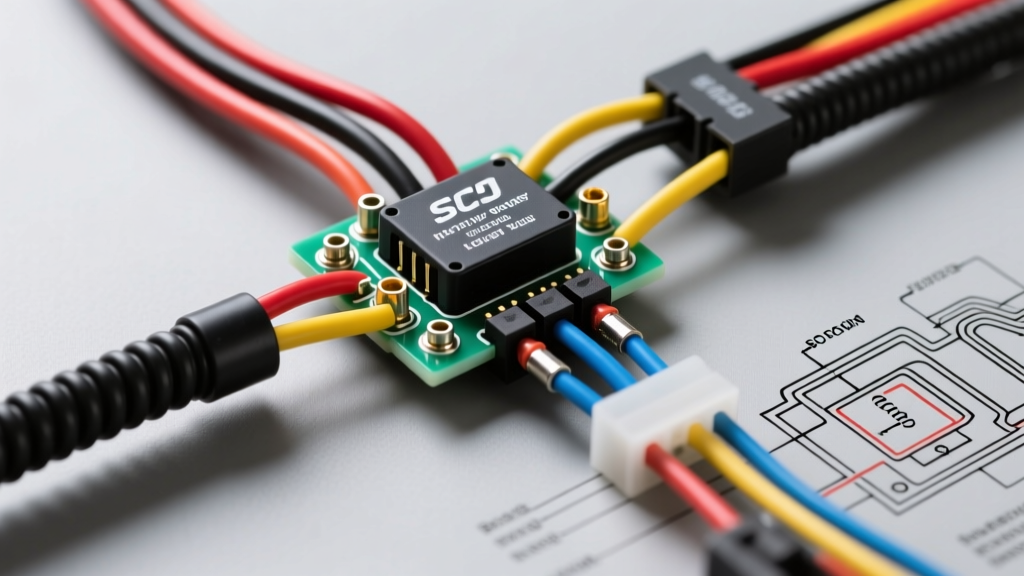
Introduction to Large-Scale RC Electrical Architecture
When analyzing a comprehensive rc car wiring diagram for large-scale vehicles (1/5 and 1/8 scale), the electrical complexity closely mirrors that of full-size automotive applications. Unlike small-scale toy-grade RC cars that rely on integrated printed circuit boards (PCBs), large-scale gas and electric RC cars utilize discrete, high-current components that require rigorous wire gauge sizing, precise pinout configurations, and strict electromagnetic interference (EMI) mitigation. Whether you are wiring a 30cc gas-powered HPI Baja 5B or a high-voltage 1/8 scale brushless EV monster truck, understanding the underlying electrical schematics is critical for preventing voltage drops, thermal failures, and signal cross-talk.
This technical specification reference breaks down the primary electrical subsystems found in large-scale RC vehicles: the Capacitor Discharge Ignition (CDI) for gas engines, the Electronic Speed Controller (ESC) power distribution for brushless EVs, and the low-voltage Receiver (RX) and servo architecture. All wire gauge recommendations align with standard SAE J1128 Low Tension Primary Cable principles, adapted for the high-flex, high-vibration environment of RC racing.
1/5 Scale Gas RC Car Wiring Diagram: CDI & Ignition Routing
Gas-powered RC cars (typically 23cc to 35cc engines) utilize a flywheel magneto and a Capacitor Discharge Ignition (CDI) module to generate the high-voltage spark required for combustion. The wiring diagram for this subsystem is relatively simple but highly sensitive to resistance and grounding faults.
Capacitor Discharge Ignition (CDI) Pinout & Routing
The CDI module acts as the brain of the ignition system, stepping up the low-voltage alternating current (AC) generated by the stator coil to the 15,000+ volts required by the spark plug. A standard 1/5 scale RC gas engine CDI harness features three primary wires:
- Stator Input Wire (White or Bare Copper): Carries the raw AC voltage from the magneto stator. This wire must be heavily insulated and routed away from the metal chassis to prevent arcing.
- Pickup Coil / Trigger Wire (Red or Blue): Connects to the Hall-effect or magnetic pickup sensor. This sensor reads the flywheel timing magnet and signals the CDI to fire. The resistance across the pickup coil should measure between 120 and 250 ohms on a multimeter.
- Ground / Kill Wire (Black): Connects to the engine block and the chassis-mounted kill switch. The CDI fires by default; it is only stopped when the kill switch grounds this wire to the chassis, shorting the ignition circuit.
Kill Switch and Chassis Grounding
In an rc car wiring diagram for gas models, the kill switch is a normally-open (NO) momentary pushbutton or a toggle switch wired in series between the CDI ground wire and the vehicle's chassis. Because large-scale RC cars often feature carbon fiber or composite chassis plates, you cannot rely on the frame for conductivity. You must run a dedicated 18 AWG stranded copper ground wire from the engine block's grounding lug directly to the receiver box ground bus and the kill switch terminal. Failure to establish a zero-resistance ground path will result in a 'no-spark' condition or erratic engine timing.
Brushless ESC & High-Amp Power Distribution (EV Models)
For 1/8 and 1/5 scale electric RC cars, the wiring diagram centers around the Electronic Speed Controller (ESC) and the high-discharge LiPo battery. Modern 150A to 200A brushless ESCs draw immense current, making wire gauge selection and connector integrity the most critical factors in the powertrain schematic.
Battery to ESC Wire Gauge (AWG) Specifications
According to Castle Creations Wire Gauge Guidelines, using undersized wire in high-amperage RC applications leads to severe voltage sag, excessive heat generation, and potential battery fires. Silicone-jacketed, high-strand-count copper wire is mandatory for its flexibility and thermal resistance.
| ESC Current Rating | Recommended Wire Gauge (AWG) | Connector Type | Max Continuous Draw |
|---|---|---|---|
| 60A - 80A | 12 AWG Silicone | XT60 / IC5 | 85A |
| 100A - 120A | 10 AWG Silicone | XT90 / IC5 | 120A |
| 150A - 200A+ | 8 AWG Silicone | QS8 (10mm) / XT90-S | 200A+ |
Anti-Spark Resistor Integration
When wiring a high-voltage ESC (6S to 8S LiPo, 22.2V - 29.6V), plugging in the battery causes a massive inrush current to charge the ESC's internal capacitors. This spark can pit and degrade the battery connectors. Advanced RC car wiring diagrams incorporate an XT90-S (Anti-Spark) connector, which features a built-in 56-ohm, 5-watt resistor on one of the positive terminals. The resistor pre-charges the capacitors over a 0.5-second delay before the main high-current contacts engage, eliminating the spark and protecting the ESC's Field Effect Transistors (FETs).
Receiver (RX) & Servo Power Architecture
The low-voltage side of the rc car wiring diagram handles Pulse Width Modulation (PWM) signals and receiver power. Signal integrity is paramount, as voltage drops or RF interference can cause a vehicle to go out of control at high speeds.
Standard 3-Pin Servo Connector Pinout
Most RC servos and receivers utilize the standard JR/Futaba 3-pin connector, featuring a 2.54mm (0.1-inch) pitch. The pinout is standardized across nearly all major brands (Futaba, Spektrum, Sanwa), though Futaba historically used a polarized tab that can be trimmed for cross-compatibility.
| Pin Number | Wire Color (Standard) | Function | Voltage / Signal Spec |
|---|---|---|---|
| Pin 1 (Ground) | Black or Brown | Negative / Ground | 0V Reference |
| Pin 2 (VCC) | Red | Positive Power | 4.8V - 8.4V DC |
| Pin 3 (Signal) | White, Yellow, or Orange | PWM Signal | 1000µs to 2000µs Pulse |
BEC vs. Standalone UBEC Power Routing
Modern ESCs include a Battery Eliminator Circuit (BEC) to step down the main LiPo voltage to 6.0V for the receiver and servos. However, linear BECs generate excessive heat when powering high-torque digital servos (which can draw 3A to 5A peak each). For large-scale RC cars utilizing multiple high-voltage (HV) servos for steering and braking, the wiring diagram should bypass the internal ESC BEC. Instead, route a dedicated 2S LiFePO4 (6.6V) receiver pack or a high-amperage Switching UBEC (10A+) directly to the receiver's 'BATT' or 'BIND' port to ensure clean, regulated power without thermal shutdown risks.
RF Interference and EMI Shielding in RC Harnesses
Large-scale RC cars generate significant Electromagnetic Interference (EMI). Brushless motors emit high-frequency noise, and gas engine spark plugs generate broadband RF noise. If low-voltage signal wires are routed parallel to high-current power wires, inductive coupling can induce voltage spikes in the PWM signal wire, causing servo jitter or sudden throttle cut-offs.
EMI Mitigation Best Practices
- Twisted Pair Routing: Always twist the CDI pickup coil wires and the servo signal wires with their respective ground wires. Twisting cancels out induced electromagnetic fields.
- Orthogonal Crossing: When the high-amp ESC battery wires must cross the receiver antenna or servo wires, ensure they cross at a strict 90-degree angle to minimize the surface area for inductive coupling.
- Ferrite Rings: Install a snap-on ferrite bead on the receiver power lead and the throttle/steering servo signal wires near the receiver to choke high-frequency EMI noise.
- Spark Plug Boot Shielding: On gas RC cars, ensure the spark plug boot contains an internal brass suppressor or use a carbon-core spark plug wire to prevent the ignition spark from broadcasting RF noise into the 2.4GHz receiver band.
Real-World Troubleshooting Decision Tree
Use this diagnostic sequence when diagnosing electrical faults based on your rc car wiring diagram:
- Symptom: Servos twitch erratically at full throttle.
- Cause: ESC BEC voltage sag under high motor load.
- Fix: Upgrade to a standalone 10A Switching UBEC or install a 2S LiFePO4 receiver pack.
- Symptom: Gas engine will not shut off via transmitter.
- Cause: Kill switch ground wire has high resistance or is disconnected from the engine block.
- Fix: Clean the engine block grounding lug, apply dielectric grease, and verify continuity to the receiver box ground bus.
- Symptom: XT90 connector melts during 1/8 scale EV runs.
- Cause: 12 AWG wire used on a 150A ESC, causing excessive resistance and heat at the solder joint.
- Fix: Upgrade to 8 AWG high-strand silicone wire and QS8 10mm bullet connectors as per Futaba RC Servo & Receiver Specifications and ESC manufacturer guidelines.
Conclusion
Building or repairing a large-scale RC car requires the same attention to detail as full-scale automotive wiring. By adhering to proper AWG sizing, understanding the distinct differences between CDI ignition grounding and ESC high-current routing, and implementing strict EMI shielding protocols, you ensure maximum reliability and performance on the track. Always verify continuity with a digital multimeter and consult your specific component manufacturer's pinout diagrams before applying power to any newly assembled RC harness.