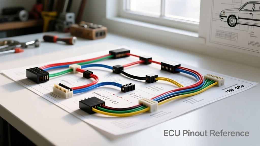
Understanding the Car Electrical System Diagram for the EK/EJ Chassis
When diagnosing or modifying a 1996-2000 Honda Civic (EK/EJ chassis), a comprehensive car electrical system diagram is your most critical tool. Unlike modern vehicles that rely on complex multiplexed CAN-bus networks, the OBD2-era Civic utilizes a highly logical, centralized PGM-FI (Programmed Fuel Injection) system. This makes the wiring schematics exceptionally straightforward to trace, provided you understand the OEM color codes, gauge specifications, and connector layouts. This complete walkthrough will dissect the primary power distribution, the notorious PGM-FI main relay, ECU pinouts, and sensor circuit topologies, giving you the actionable data needed for precise diagnostics and aftermarket integration.
Navigating the Car Electrical System Diagram: Power Distribution
The foundation of any automotive wiring schematic begins at the battery and the primary fuse boxes. In the 96-00 Civic, the main power feed from the positive battery terminal to the under-hood fuse/relay box is a heavy-duty 10 AWG red wire. This circuit is protected by a 100A main fusible link. According to SAE J1128 standards for low-tension primary cable, a 10 AWG copper wire can safely handle up to 55 amps continuously, but the 100A link is designed to protect against catastrophic dead shorts in the main harness.
From the under-hood box, power is distributed to the under-dash fuse panel via a 14 AWG white/red (WHT/RED) wire, protected by a 50A backup fuse. When reading the car electrical system diagram, always verify voltage at these primary distribution nodes before tracing individual circuits. A common failure mode in aging Civics is corrosion at the under-hood fuse box internal bus bars, leading to a 1.5V to 2.0V drop under load, which can cause erratic ECU behavior and fuel pump starvation.
Primary Power Distribution Specifications
| Circuit Origin | Wire Color | AWG Size | Protection | Destination |
|---|---|---|---|---|
| Battery (+) | Red | 10 AWG | 100A Fusible Link | Under-Hood Fuse Box |
| Under-Hood Box | White/Red | 14 AWG | 50A Backup Fuse | Under-Dash Fuse Panel |
| Ignition Switch (IG1) | Black/Yellow | 16 AWG | 15A ACG Fuse | PGM-FI Main Relay & ECU |
| Ignition Switch (IG2) | Yellow/White | 16 AWG | 15A Radio Fuse | Accessories & HVAC |
The PGM-FI Main Relay: Heart of the Honda Electrical System
No walkthrough of a Honda car electrical system diagram is complete without addressing the PGM-FI Main Relay. Located under the driver's side dash, this 7-pin relay acts as the primary gatekeeper for the fuel pump, ECU, and fuel injectors. The most frequent cause of a no-start condition in hot weather (often called the "hot soak" failure) is the fracturing of internal solder joints on the relay's printed circuit board due to thermal expansion and contraction.
When testing the main relay, you must verify both the control side (coil) and the load side (switched power). Pin 5 receives the IG1 signal from the ignition switch. When the ECU grounds Pin 4, the internal coil energizes, closing the contacts to send 12V from Pin 7 to Pin 2 (Fuel Pump) and Pin 3 (ECU/Injectors).
PGM-FI Main Relay 7-Pin Connector Pinout
| Pin | Wire Color | Function | Voltage State (Key ON) |
|---|---|---|---|
| 1 | Black/Yellow | 12V Battery Feed (Constant) | 12.6V |
| 2 | Yellow/Black | Output to Fuel Pump | 12.6V (Primes for 2s) |
| 3 | Yellow/Green | Output to ECU & Injectors | 12.6V |
| 4 | Black | ECU Controlled Ground | 0V (Energized) / Open |
| 5 | Black/Yellow | IG1 Ignition Feed | 12.6V |
| 6 | White/Blue | Starter Signal (Bypass) | 12.6V (Cranking only) |
| 7 | White/Red | 12V Battery Feed (Constant) | 12.6V |
ECU/PCM Pinout Walkthrough (P2T ECU Configuration)
The 1996-2000 Civic EX/Si utilizes the P2T ECU, which features three distinct connectors: Connector A (32-pin, Power/Ground), Connector B (25-pin, Sensors), and Connector C (25-pin, Actuators). When referencing your car electrical system diagram, it is vital to understand that Honda uses a standardized color-coding system for ECU grounds. Almost all solid Black (BLK) wires terminating at the ECU are ground circuits.
Connector A handles the heavy lifting for power and grounding. Pins A17 through A20, as well as A23 through A26, are all solid Black wires that route to the primary engine ground location (G101) on the thermostat housing. If your vehicle is experiencing erratic idle or random misfires, perform a voltage drop test across these specific ECU pins to the engine block. A reading above 0.05V indicates a corroded ground strap or a failing G101 connection.
ECU Connector A: Critical Power and Ground Pins
| Pin Number | Wire Color | Circuit Description | Diagnostic Note |
|---|---|---|---|
| A1 | White/Red | Backup Power (Constant 12V) | Maintains ECU memory. Check if losing radio presets. |
| A3 | Yellow/Black | IG1 Power Feed | Must read full battery voltage with key in ON position. |
| A17 - A20 | Black | Logic Ground (PGM-FI) | Routes to G101. Torque to 22 lb-ft. |
| A23 - A26 | Black | Power Ground (Injectors) | Handles high-current injector return pulses. |
Sensor Circuit Topologies: MAP, TPS, and O2 Sensors
Modern automotive diagnostics require a deep understanding of 5-volt reference circuits. The car electrical system diagram reveals that the ECU provides a highly regulated 5V reference to the Manifold Absolute Pressure (MAP) sensor and the Throttle Position Sensor (TPS). These circuits utilize a 3-wire topology: 5V Reference, Signal Return, and Sensor Ground.
For the MAP Sensor, Pin 1 (Yellow/White) receives the 5V reference. Pin 2 (Green/White) is the signal return, which should read approximately 2.8V at sea level with the key on and engine off (KOEO), dropping to 1.0V - 1.5V at a hot idle. Pin 3 (Black/White) is the dedicated sensor ground. It is crucial to note that the sensor ground (Black/White) is isolated inside the ECU and is not the same as the chassis ground (Black). Splicing a MAP sensor ground into the chassis will introduce alternator whine and electrical noise into the signal return, causing severe fueling errors.
The Primary Oxygen (O2) Sensor in these models is a 4-wire heated exhaust gas oxygen (HEGO) sensor. The heater circuit is powered by a White wire (12V from the main relay) and grounded by the ECU via a Black/White wire to allow the ECU to control heater warm-up times. The actual sensing element uses a Green wire for the signal output (0.1V to 0.9V oscillating) and a Black wire for the signal ground. When testing the O2 heater circuit, expect a resistance reading between 4.0 and 6.0 ohms across the heater pins at room temperature, as outlined in standard automotive electrical diagnostic guides.
Grounding Strategy and Real-World Failure Modes
The most overlooked aspect of any car electrical system diagram is the physical grounding strategy. Honda relies heavily on the G101 ground point, located on the back of the cylinder head near the thermostat housing. This single 10mm bolt secures the engine wiring harness grounds, including the ECU logic grounds and the ignition coil ground.
Pro-Tip for Restorations and Swaps: When reassembling the G101 ground, you must clean the mating surface on the aluminum cylinder head down to bare metal using a wire wheel. Apply a thin layer of dielectric grease only after torquing the bolt to 22 lb-ft to prevent future galvanic corrosion. The main battery ground to the transmission bell housing (G102) uses a thicker 8 AWG wire and a 12mm bolt, requiring 33 lb-ft of torque. If your starter clicks but fails to crank the engine, or if your headlights pulse in time with the turn signals, a high-resistance failure at G102 is the primary suspect.
Troubleshooting the Fuel Pump Circuit via the Schematic
When utilizing the car electrical system diagram to diagnose a dead fuel pump, avoid the rookie mistake of immediately replacing the pump. Instead, trace the circuit backward. 1. Verify 12V at the fuel pump relay output (Yellow/Black wire) in the trunk for the first two seconds after turning the key to the ON position. 2. If voltage is absent, check the 15A ACG (S) fuse in the under-hood box. 3. If the fuse is intact, test the PGM-FI main relay Pin 2 for continuity to the fuel pump harness connector. 4. Finally, verify the fuel pump ground point (G501) located behind the rear passenger side taillight. The ground wire is solid Black (18 AWG). A corroded G501 will cause the fuel pump to draw excessive amperage, eventually melting the relay contacts or blowing the ACG fuse.
By mastering the specific wire colors, AWG ratings, and pin configurations detailed in this walkthrough, you can confidently diagnose, repair, and modify the 1996-2000 Honda Civic electrical system without relying on guesswork or trial-and-error parts swapping.