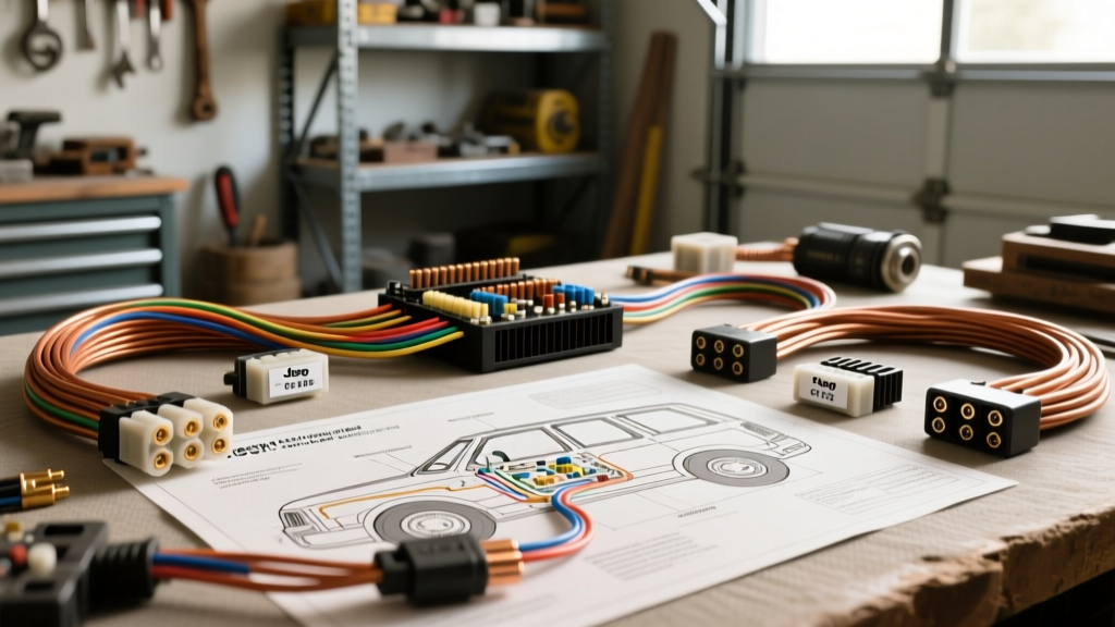
Why the Factory Jeep Grand Cherokee WJ Electrical Wiring Diagram PDF is Mandatory
The 1999-2004 Jeep Grand Cherokee (WJ generation) represents a pivotal shift in Chrysler's electrical architecture. Unlike the older ZJ generation, the WJ introduced the Programmable Communications Interface (PCI) data bus, multiplexed lighting controls via the Body Control Module (BCM), and a PCM-controlled alternator field circuit. When performing aftermarket installations, relying on generic universal wiring schematics will inevitably lead to blown fuses, fried control modules, or parasitic battery draws. Utilizing the exact Jeep Grand Cherokee WJ electrical wiring diagram PDF is the only way to accurately trace cavity pinouts, identify splice locations, and verify wire gauge requirements before cutting into the factory harness.
In this practical how-to installation guide, we will use the factory Mopar diagram data to walk you through installing a 7-way RV trailer tow harness and upgrading the PCM-controlled charging system. We will cover specific Metri-Pack connector cavities, AWG wire sizing, and critical ground points that frequently fail on the WJ platform.
Required Tools and Materials for WJ Harness Modification
Before intercepting any circuits shown in the wiring diagram PDF, ensure you have the correct automotive-grade materials. The WJ uses predominantly Delphi (Packard) Metri-Pack 280 series terminals for lighting and Weather-Pack seals for exterior connections.
- Wire: 10 AWG GXL (Cross-linked Polyethylene) for auxiliary power feeds; 14 AWG GXL for lighting signals.
- Crimpers: Delphi Metri-Pack 280 crimp tool (or equivalent precision die) to ensure proper bellmouth crimps without damaging the wire strands.
- Sealing: Adhesive-lined dual-wall heat shrink tubing and Mopar Dielectric Grease (Part #05013471AA) for all exterior cavities.
- Testing: High-impedance digital multimeter (DMM) and a PCI-bus safe logic probe (standard test lights will short the 5V data bus).
Step-by-Step: Installing the 7-Way Trailer Tow Harness
Many WJ owners attempt to tap into the rear tail lights using scotch-locks. The wiring diagram explicitly warns against this due to the BCM's solid-state lighting drivers, which monitor current draw to detect bulb outages. Adding trailer loads directly to the BCM output circuits will trigger a 'Lamp Out' error and cause the BCM to shut down the circuit. The proper method, as outlined in the Mopar accessory diagrams, is to use the factory rear body harness connector as an intercept point and install heavy-duty relays.
Step 1: Intercepting the Rear Lighting Circuit (Connectors C304 & C305)
Locate the rear lighting connectors under the rear quarter panels. According to the diagram, Connector C304 services the left rear, and C305 services the right rear. You will need to depin the factory terminals and insert new Metri-Pack 280 pigtail wires to act as relay triggers, preserving the factory circuit integrity.
- Tail/Park Lights: Intercept the Black/Pink wire (Cavity 2 on C304/C305).
- Left Stop/Turn: Intercept the Dark Green/Red wire (Cavity 1 on C304).
- Right Stop/Turn: Intercept the Brown/Yellow wire (Cavity 1 on C305).
Route these 14 AWG trigger wires forward to a centralized relay box mounted near the rear cargo area, ensuring they are wrapped in split-loom tubing and secured away from the rear wiper motor linkage.
Step 2: Routing the 10 AWG Auxiliary Power Feed
The trailer harness requires a dedicated 30A fused power feed for the trailer's auxiliary 12V pin and the relay power buses. The wiring diagram shows the Power Distribution Center (PDC) under the hood has an open auxiliary stud. Run a 10 AWG Black/Orange wire from the PDC auxiliary stud, routing it through the firewall grommet shared with the ABS harness (Connector C100), down the driver-side frame rail, to the rear relay box. Never use 12 AWG or 14 AWG for the main trailer power feed, as voltage drop over the 15-foot run will cause trailer brake controller instability.
Step 3: Terminating the 7-Way RV Blade Connector
Using the standard SAE J286 color code mapped to your WJ relay outputs, terminate the rear bumper 7-way connector. Apply dielectric grease to all cavities to prevent the green corrosion common on WJ trailer plugs exposed to road salt.
Upgrading the PCM-Controlled Alternator (Field & Sense Wiring)
A common WJ upgrade is swapping the stock 117A alternator for a 160A unit to support off-road lighting and winching. The Jeep Grand Cherokee WJ electrical wiring diagram PDF reveals that the alternator is not internally regulated. The Powertrain Control Module (PCM) controls the alternator's field and monitors the system sense voltage.
If you are upgrading the alternator or diagnosing a 'Battery Temp Sensor' code, you must verify the following circuits at PCM Connector C1:
- Generator Field (Dark Green): PCM C1, Pin 20. This is a Pulse Width Modulated (PWM) ground circuit. The PCM rapidly switches this ground to control rotor magnetism.
- Generator Sense (Dark Green/Orange): PCM C1, Pin 19. This wire tells the PCM the actual voltage at the alternator B+ post.
Installation Tip: When upgrading to a high-output alternator, you must also upgrade the main B+ charge cable from 4 AWG to 2 AWG or 1/0 AWG. If the cable is undersized, the PCM will read a lower voltage on the Sense wire (Pin 19) and aggressively over-field the alternator, leading to premature rotor failure.
WJ Rear Lighting & Trailer Pinout Reference Table
| 7-Way RV Pin | Function | WJ Relay Trigger Source (Diagram Color) | Wire Gauge (Feed) |
|---|---|---|---|
| Pin 1 | Left Turn / Stop | Dark Green/Red (C304 Cavity 1) | 14 AWG (Trigger) / 12 AWG (Load) |
| Pin 2 | Rear Fog / Aux | Not Factory Equipped (Run from PDC) | 12 AWG |
| Pin 3 | Ground | Chassis Ground (10 AWG to Frame) | 10 AWG |
| Pin 4 | Right Turn / Stop | Brown/Yellow (C305 Cavity 1) | 14 AWG (Trigger) / 12 AWG (Load) |
| Pin 5 | Right Tail / Marker | Black/Pink (C305 Cavity 2) | 14 AWG (Trigger) / 12 AWG (Load) |
| Pin 6 | Left Tail / Marker | Black/Pink (C304 Cavity 2) | 14 AWG (Trigger) / 12 AWG (Load) |
| Pin 7 | 12V Auxiliary Power | PDC Aux Stud (Fused 30A) | 10 AWG |
Real-World WJ Failure Modes: Grounds and Data Bus Shorts
When troubleshooting issues post-installation, the wiring diagram PDF points to two critical failure areas unique to the WJ platform:
1. Ground G401 Corrosion (Left Kick Panel)
Ground G401 is the primary ground for the BCM and the PCI data bus. It is located behind the left kick panel, directly above the hood release lever. Water ingress from a clogged sunroof drain or a leaking windshield seal will pool exactly on this ground stud. Corrosion here increases resistance, causing the PCI bus voltage to drop below the 2.5V threshold. This results in erratic gauge cluster behavior, phantom alarm triggers, and a 'No Bus' error on the odometer display. Fix: Remove the G401 bolt, clean the ring terminals and body sheet metal with a wire brush, apply conductive anti-corrosion compound, and torque to 85 in-lbs.
2. PCI Bus Shorts During Harness Routing
The PCI bus wire (Violet/Yellow) is a single-wire multiplex network operating at 5V. When routing new trailer harness wires through the firewall grommet (C100) or the kick panels, it is incredibly easy to accidentally pinch or pierce the Violet/Yellow wire. A dead short to ground on the PCI bus will instantly prevent the PCM and SKIM (Sentry Key Immobilizer Module) from communicating, resulting in a crank-no-start condition. Always use a blunt trim panel tool to fish wires through grommets, and never use self-tapping screws near the BCM or PCM harness trunks.
Authoritative References
For further diagnostic trees and complete connector cavity maps, consult the following authoritative resources:
- WJ Jeeps Technical Wiring Archive - The definitive community-driven repository for WJ-specific connector locations, ground maps, and PCM pinout cross-references.
- Mopar Connection Repair System - Official Stellantis/FCA documentation for Metri-Pack and Weather-Pack terminal part numbers, pigtail kits, and proper crimp die specifications.
- SAE J1113 Electromagnetic Compatibility Standards - Guidelines for routing high-current trailer feeds away from low-voltage data buses (like the WJ's PCI bus) to prevent electromagnetic interference.
By strictly adhering to the factory Jeep Grand Cherokee WJ electrical wiring diagram PDF and utilizing proper automotive termination methods, you ensure your aftermarket upgrades are safe, reliable, and fully integrated with the vehicle's complex multiplexed architecture.