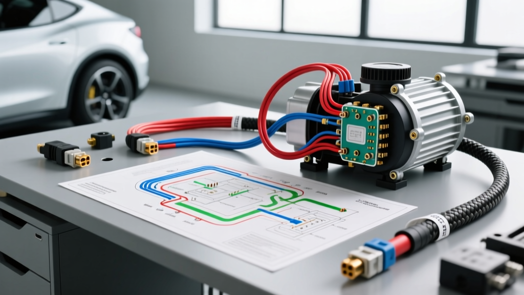
Introduction to EV Thermal Management Systems
In modern Electric Vehicles (EVs) and Plug-in Hybrid Electric Vehicles (PHEVs), cabin heating and battery thermal regulation are no longer handled by simple resistive PTC heaters. Instead, high-efficiency automotive heat pumps are utilized to scavenge ambient and drivetrain waste heat. When diagnosing thermal management faults or performing a compressor replacement, accessing an accurate wiring diagram for heat pump circuits is critical. Unlike traditional A/C compressors driven by a serpentine belt, EV heat pump compressors are powered by a high-voltage (HV) 3-phase AC inverter and controlled via low-voltage (LV) digital communication networks.
This practical installation and wiring guide covers the integration of a generic 400V-class EV heat pump compressor, detailing high-voltage safety, LV control pinouts, shielded cable termination, and dielectric oil requirements.
Critical High-Voltage Safety Protocols
Before consulting any wiring schematics or disconnecting terminals, technicians must adhere to strict HV safety standards. The heat pump compressor operates on the main traction battery bus, typically ranging from 350V to 800V DC.
- Personal Protective Equipment (PPE): Always wear ASTM D120-rated Class 0 (1000V) insulated gloves with leather protectors.
- Vehicle Lockout/Tagout (LOTO): Disconnect the 12V auxiliary battery and pull the Manual Service Disconnect (MSD) or open the HV contactors via OEM scan tool commands.
- Verification: Wait 15 minutes for the inverter capacitors to discharge. Verify 0V using a CAT III or CAT IV rated digital multimeter (DMM) across the HV terminals and from each terminal to the chassis ground.
- Isolation Testing: Ensure your testing equipment meets SAE J2344 guidelines for EV safety to prevent accidental short circuits during probing.
EV Heat Pump Wiring Diagram Breakdown
The electrical architecture of an EV heat pump is divided into two distinct circuits: the High-Voltage (HV) power delivery circuit and the Low-Voltage (LV) control and communication circuit.
1. High-Voltage (HV) Power Circuit
The HV circuit supplies 3-phase AC power from the vehicle's main inverter or a dedicated thermal management inverter to the compressor's internal motor. Because the compressor is mounted on the vehicle chassis, the HV cabling must be fully shielded to prevent electromagnetic interference (EMI) from disrupting the vehicle's CAN bus or resolver sensors.
- Cable Specification: 2 AWG or 4 AWG (depending on max kW draw, typically 6kW-10kW) shielded EV cable (e.g., LEONI or Huber+Suhner).
- Jacket Color: Bright orange (mandated by ISO 6722 for HV identification).
- Shielding Termination: The braided copper shield must be terminated using a 360-degree shield ring and heat-shrink tubing, grounding the EMI directly to the inverter housing and compressor chassis.
- HV Interlock Loop (HVIL): A low-current (18 AWG) loop runs through the HV connector. If the connector is partially unseated, the HVIL circuit breaks, instantly commanding the main battery contactors to open.
2. Low-Voltage (LV) Control & Communication Circuit
The compressor's internal controller requires a 12V reference, a chassis ground, and a communication line to receive speed and displacement commands from the Thermal Management Control Module (TMCM). Most modern EV compressors utilize a LIN (Local Interconnect Network) bus or a dedicated CAN bus for this signaling.
Thermal Management Control Module Pinout Table
Below is a standard 6-pin LV control connector pinout commonly found on 400V-class EV heat pump compressors (e.g., Denso or Hanon Systems units). Always verify against your specific OEM service manual.
| Pin | Function | Wire Color | AWG Size | Circuit Notes & Specifications |
|---|---|---|---|---|
| 1 | 12V Battery Power (B+) | Red | 16 AWG | Fused at 15A. Supplies internal ECU and LIN transceiver. |
| 2 | Chassis Ground (GND) | Black | 16 AWG | Must have < 0.5 ohms resistance to battery negative. |
| 3 | LIN Bus / CAN High | Yellow/Green | 20 AWG | Twisted pair. 12V square wave (LIN) or 2.5V bias (CAN). |
| 4 | LIN Ground / CAN Low | White | 20 AWG | Twisted pair shield drain wire must be grounded at TMCM. |
| 5 | Wake-Up / Enable Signal | Blue | 18 AWG | 12V pulse from Body Control Module (BCM) to wake inverter. |
| 6 | Diagnostic / Factory Test | Violet | 22 AWG | Typically capped. Used for OEM bench flashing. |
Step-by-Step Heat Pump Compressor Installation
Follow these steps to ensure a safe, leak-free, and electrically sound installation of the replacement heat pump compressor.
- Refrigerant Recovery & Oil Drain: Recover R1234yf or R134a refrigerant using an EV-certified recovery machine. Drain the old compressor's dielectric oil and measure the volume.
- Dielectric Oil Preparation: Critical Warning: Never use standard PAG oil in an EV heat pump compressor. PAG oil is highly conductive and will cause a catastrophic HV isolation fault. You must use high-dielectric POE (Polyolester) oil or OEM-specific ND-OIL 11. Add the exact volume of new oil to the replacement compressor.
- Mounting & Torque: Install the compressor onto the chassis isolation mounts. Torque the M10 mounting bolts to 25 Nm. Ensure the rubber isolation bushings are intact to prevent NVH (Noise, Vibration, and Harshness) transfer to the cabin.
- LV Harness Connection: Apply a small amount of dielectric grease to the 6-pin LV connector. Mate the connector until the primary and secondary locking tabs click. Secure the harness with a P-clip, maintaining at least 50mm of clearance from any moving belts or hot refrigerant lines.
- HV Cable Termination: Inspect the orange HV cable lugs for corrosion or frayed shielding. Apply a thin layer of electrical contact cleaner. Mate the HV connector to the compressor. You must hear the definitive 'click' of the HVIL secondary lock.
- Torque HV Terminals: If your system uses bolted HV lugs rather than a plug-in connector, torque the M8 terminal nuts to exactly 20 Nm. Over-torquing will strip the compressor's internal inverter board threads; under-torquing will cause arcing and thermal meltdown.
- Vacuum & Leak Test: Pull a deep vacuum to 500 microns for 30 minutes to remove moisture (which degrades POE oil and causes HV faults). Perform a nitrogen pressure test at 150 PSI before charging with refrigerant.
Real-World Troubleshooting & CAN Bus Diagnostics
If the heat pump fails to engage post-installation, rely on your wiring diagram and an oscilloscope rather than blindly swapping parts.
- HV Isolation Fault (DTC P0A09 or similar): The vehicle's Battery Management System (BMS) has detected a leak to ground. This is almost always caused by the wrong A/C oil (PAG instead of POE), moisture in the refrigerant, or a pinched orange HV cable where the shielding is touching the chassis.
- LIN Bus Communication Failure: Connect an oscilloscope to Pin 3. A healthy LIN bus will show a clean 12V square wave transitioning between 0V and 12V at roughly 19.2 kbps. If the signal is rounded or stuck at 12V, check for a short to B+ or a broken ground on Pin 2. For deeper network diagnostics, refer to I-CAR's EV network troubleshooting protocols.
- Compressor Whine / NVH: If the compressor runs but produces a loud whine, the 3-phase HV waveforms may be degraded due to high resistance in the HV interlock or a corroded terminal lug, causing the internal inverter to misfire the stator phases.
Summary
Successfully wiring and installing an EV heat pump requires a departure from traditional 12V A/C clutch diagnostics. By strictly adhering to HV safety protocols, utilizing the correct dielectric fluids, and understanding the LIN/CAN bus pinouts detailed in your wiring diagram for heat pump systems, you can reliably restore vital cabin heating and battery thermal management functions. Always consult the specific OEM service manual and NFPA 70E standards before interacting with high-voltage EV architectures.