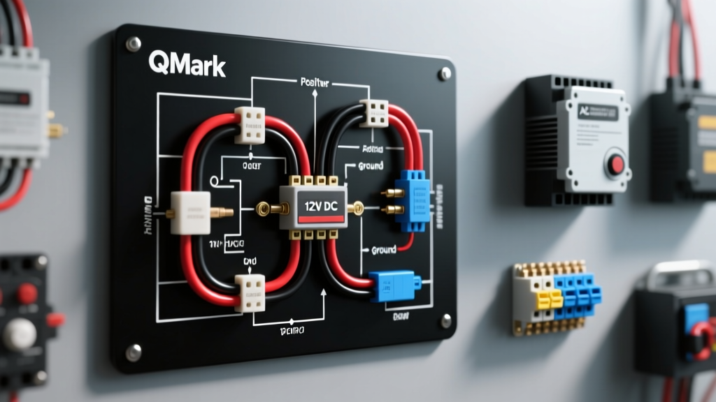
Adapting the QMark Heater Wiring Diagram for Mobile Applications
QMark electric heaters, manufactured by Marley Engineered Products, are the gold standard for commercial and industrial space heating. While traditionally deployed in fixed residential or warehouse environments, heavy-duty QMark models—specifically the MUH (Unit Heater) and BR (Baseboard) series—are increasingly being integrated into mobile platforms. Fleet upfitters, custom RV builders, and transit bus technicians frequently utilize these robust, forced-air or convection heaters to maintain climate control in utility truck cargo beds, mobile command centers, and luxury RV basements.
However, adapting a standard QMark heater wiring diagram for a vehicle requires bridging the gap between fixed 120V/240V AC grid power and a mobile 12V DC electrical architecture. You cannot simply wire a QMark heater directly to a vehicle's alternator. Instead, the installation requires a high-capacity Pure Sine Wave inverter, a dedicated 12V DC ignition-sense control circuit, and strict adherence to mobile grounding standards to prevent catastrophic electrical faults. This practical how-to guide details the exact specifications, wire gauges, and relay pinouts required to safely install and control a 120V AC QMark heater in a mobile automotive environment.
Electrical Specifications and Component Sizing
Before cutting into your vehicle's wiring harness, you must properly size your components. A standard 1500W QMark MUH unit heater draws approximately 12.5 Amps at 120V AC. On the DC side of the inverter, accounting for an 85% efficiency rate, this translates to a continuous draw of over 145 Amps from the battery bank. The table below outlines the mandatory specifications for a safe, code-compliant mobile installation.
| Component | Specification | Mobile Standard / Requirement |
|---|---|---|
| Inverter | 2000W+ Pure Sine Wave | Must be Pure Sine to prevent QMark contactor buzz and transformer overheating. |
| DC Battery Cables | 1/0 AWG Welding Cable | SAE J1128 compliant; stranded copper to withstand vehicular vibration. |
| DC Overcurrent Protection | 200A ANL Fuse | Installed within 18 inches of the positive battery terminal. |
| AC Load Wiring | 12 AWG MTW (Stranded) | Machine Tool Wire; standard solid THHN will fracture under road vibration. |
| Control Relay | Bosch-Style ISO Mini (40A) | Used to switch the inverter's remote wake-up circuit via ignition sense. |
Step-by-Step Installation Guide
Step 1: Sizing the Pure Sine Wave Inverter and DC Feed
The most common failure point in mobile AC heating systems is inverter clipping and contactor degradation. QMark unit heaters utilize internal electromagnetic contactors and step-down transformers for the fan motor and thermostat logic. If you attempt to power a QMark heater using a Modified Sine Wave (MSW) inverter, the harmonic distortion will cause the contactor to chatter violently, generating excessive heat and ultimately welding the contacts shut. According to the Marley Engineered Products Technical Resource Center, clean power is essential for the longevity of their internal relays. Always use a 2000W or larger Pure Sine Wave (PSW) inverter.
Run 1/0 AWG SAE J1128 compliant stranded welding cable from the vehicle's battery bank to the inverter. Because a 1500W heating element creates a massive continuous load, voltage drop is a critical concern. Keep the DC cable run under 10 feet whenever possible. Crimp the terminals using a hydraulic crimper and seal them with adhesive-lined heat shrink. Torque the inverter busbar nuts to the manufacturer's specification (typically 10-12 ft-lbs) and apply a torque seal marker to monitor for vibration-induced loosening over time.
Step 2: Wiring the 12V DC Ignition-Sense Control Circuit
In a mobile environment, leaving a 1500W heater powered on while the engine is off will rapidly deplete the chassis battery, potentially leaving the vehicle stranded. To prevent this, we wire a 12V DC ignition-sense circuit that only allows the inverter to power the QMark heater when the vehicle's ignition is in the 'Run' position, or when a dedicated auxiliary generator is active.
Utilize a standard 4-pin Bosch-style ISO mini relay to control the inverter's 'Remote On' terminal. The relay pinout is as follows:
- Pin 86 (Coil +): Connect to a 12V ignition-switched source (typically a Blue wire in automotive harnesses). Use an add-a-circuit fuse tap at the fuse box, protected by a 5A fuse.
- Pin 85 (Coil -): Connect to a clean, bare-metal chassis ground using a ring terminal and a self-tapping star washer. (White or Black wire).
- Pin 30 (Common): Connect to a 12V constant battery source, protected by an inline 10A ATC fuse. (Red wire).
- Pin 87 (Normally Open): Connect to the 'Remote On' or 'Ignition Sense' terminal on your inverter. When the ignition turns on, the relay closes, sending 12V to the inverter, waking it up to supply AC power to the QMark heater.
Step 3: Routing and Terminating the 120V AC Load
When referencing the standard QMark MUH wiring diagram, you will see terminals designated for L1 (Line), L2 (Neutral), and Ground. For 120V AC single-phase mobile applications, L1 is your Hot wire (Black), and L2 is your Neutral wire (White).
Route 12 AWG MTW (Machine Tool Wire) from the inverter's AC output breaker panel to the QMark heater's junction box. MTW is heavily stranded and features a flexible, oil-resistant jacket that is vastly superior to rigid residential Romex or solid-core THHN, which will snap under the constant micro-vibrations of a moving truck or RV. Secure the AC wiring every 18 inches using UV-resistant cable ties and adhesive mounts, ensuring the wires do not chafe against the vehicle's metal ribs.
At the QMark terminal block, strip the wires precisely to 5/16 inch. Insert them into the terminal block and torque the set screws to 14 in-lbs. Over-torquing will sever the fine strands of the MTW wire, creating a high-resistance hot spot that can melt the junction box.
Step 4: Mobile Grounding and RVIA Compliance
Grounding an AC appliance in a vehicle is fundamentally different from grounding it in a house. The RV Industry Association (RVIA) ANSI/RVIA LV Standards strictly dictate how AC grounds must be handled in mobile environments to prevent the vehicle's metal chassis from becoming energized in the event of a short circuit.
The Green/Bare ground wire from the QMark heater must be routed back to a dedicated AC Grounding Bus Bar located inside the inverter's AC distribution panel. Do not bond the QMark's AC ground wire directly to the vehicle's steel frame. The inverter internally bonds the AC Neutral and AC Ground when operating in standalone (off-grid) mode. If you create a secondary ground path to the chassis, you risk creating a ground loop, which will cause the inverter's internal GFCI (Ground Fault Circuit Interrupter) to trip immediately upon the heater's contactor engaging.
Troubleshooting Common Mobile Heating Failures
Even with a flawless installation, the harsh environment of a commercial work truck or RV can introduce electrical anomalies. Use this diagnostic tree to troubleshoot common issues:
- Symptom: QMark contactor hums loudly but the heating element does not engage.
Cause: Modified Sine Wave distortion or severe DC voltage drop.
Fix: Verify the inverter is outputting a true sine wave using an oscilloscope. Check DC battery connections for corrosion. If voltage at the inverter drops below 10.5V DC under load, the inverter will clip the AC waveform, starving the QMark contactor coil of the voltage required to fully close the mechanical gap. - Symptom: Inverter GFCI trips instantly when the QMark thermostat calls for heat.
Cause: Improper Neutral-Ground bonding or moisture ingress in the cargo bay.
Fix: Ensure the AC ground is isolated from the vehicle chassis and returns only to the inverter's ground bus. Inspect the QMark junction box for condensation; apply dielectric grease to the terminal block and install a silicone gasket seal on the junction box lid. - Symptom: Heater operates, but the internal blower fan stutters or runs backward.
Cause: Phase reversal or failing start capacitor due to inverter frequency drift.
Fix: Ensure the inverter is strictly calibrated to 60Hz. Some programmable inverters default to 50Hz for marine applications, which will severely disrupt the QMark fan motor's start winding and centrifugal switch operation.
Safety and Maintenance Protocols
Integrating high-wattage resistive heating elements into a 12V automotive system pushes the boundaries of mobile electrical design. Always adhere to SAE J1128 Low Tension Primary Cable Standards when selecting DC wiring, and never undersize your overcurrent protection. Perform a bi-annual maintenance check on the QMark heater's terminal block and the inverter's DC busbars, re-torquing all connections to spec. Road vibration inevitably causes thermal cycling and metal creep, which can loosen lugs and lead to arcing. By respecting both the QMark factory wiring schematics and mobile electrical codes, you can ensure reliable, safe, and efficient cargo bay heating for years to come.