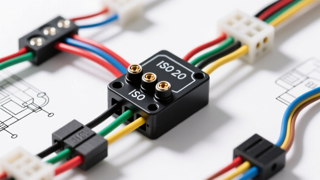
Understanding the ISO Mini 5-Pin Car Relay Pinout
The ISO mini 5-pin relay (often referred to as a Bosch-style relay) is the fundamental building block of modern automotive electrical systems. Whether you are diagnosing a GM fuel pump circuit, a Ford PCM power feed, or a Chrysler cooling fan module, understanding the exact car relay pinout is critical for accurate troubleshooting. Unlike simple 4-pin relays, the 5-pin variant includes a Normally Closed (NC) contact, allowing for complex logic states such as resistor bypasses during engine cranking or dual-speed fan operations.
Before grabbing a multimeter, you must understand the physical footprint and the standard DIN/ISO numbering convention stamped into the relay casing. The pins are not arranged sequentially; they follow a specific logical mapping designed to isolate the low-current control circuit from the high-current load circuit.
Standard ISO Mini 5-Pin Relay Specification Chart
| Pin Number | Function | Typical OEM Wire Color (GM/Ford) | Standard AWG Size | Circuit Type |
|---|---|---|---|---|
| 30 | Common Power Input (Feed) | Red / Orange / Light Green | 12 - 10 AWG | High-Current Load |
| 85 | Coil Control 1 (Usually Ground) | Black / Pink-White Tracer | 18 - 16 AWG | Low-Current Control |
| 86 | Coil Control 2 (Usually Switched 12V) | Dark Green / Yellow-Green | 18 - 16 AWG | Low-Current Control |
| 87 | Normally Open (NO) Output | Dark Blue / Purple / Gray | 12 - 10 AWG | High-Current Load |
| 87a | Normally Closed (NC) Output | Light Blue / Yellow / Tan | 12 - 10 AWG | High-Current Load |
Step-by-Step Diagnostic Troubleshooting Flow
When a relay-controlled component fails (e.g., A/C compressor clutch not engaging, or headlights stuck on), do not immediately replace the relay. Follow this structured diagnostic flow to isolate the fault to the control circuit, the load circuit, or the relay itself. This methodology aligns with ASE Electrical/Electronic Systems (A6) diagnostic guidelines.
Phase 1: Verify the Control Circuit (Pins 85 & 86)
The control circuit energizes the electromagnetic coil. If the coil does not pull the armature, the load circuit will never switch.
- Test for Coil Voltage: With the ignition ON and the circuit commanded active (e.g., A/C button pressed), back-probe Pins 85 and 86 at the fuse box socket using a digital multimeter (DMM). You should read within 0.5V of battery voltage (approx. 12.2V - 12.6V). If you read 0V, the fault lies in the wiring harness, BCM, or PCM driver.
- Test Coil Resistance (Bench Test): Remove the relay. Set your DMM to Ohms (Ω). Place probes on Pins 85 and 86. A healthy 12V automotive relay coil will typically read between 65 and 90 ohms.
- Reading near 0 Ω: The coil is internally shorted. This will often blow the control circuit fuse or damage the PCM driver transistor.
- Reading OL (Infinite): The coil wire is broken internally. Replace the relay.
Phase 2: Verify the Power Feed (Pin 30)
Pin 30 is the constant or ignition-switched high-current feed.
- Voltage Check: Probe Pin 30 in the fuse box socket. You must have full battery voltage (12.0V+).
- Voltage Drop Test: If the component operates weakly (e.g., fuel pump whines but lacks pressure), perform a voltage drop test. Place the red DMM probe on the battery positive post and the black probe on Pin 30. A reading higher than 0.2V indicates high resistance in the feed wire, a corroded fusible link, or a failing ignition switch.
Phase 3: Test the Load Switching (Pins 87 & 87a)
This is where the relay actually delivers power to the component.
- Normally Open (Pin 87) Continuity: With the relay removed and the circuit OFF, probe Pin 87. There should be no voltage. Command the circuit ON (or jump Pins 30 and 87 in the socket with a fused jumper wire). If the component turns on, the load wiring and ground are good, confirming the relay or control circuit is the culprit.
- Contact Resistance Test: When a relay is energized, the internal contacts press together. Over time, arcing causes carbon buildup or pitting. To test this, energize the relay on the bench by applying 12V to 86 and Ground to 85. Measure resistance between Pin 30 and Pin 87. It should be less than 0.1 ohms. Anything higher means the contacts are burned, causing a severe voltage drop under load.
Advanced Diagnostics: Internal Diodes and Pin 87a Logic
Not all 5-pin relays are simple mechanical switches. Modern vehicles utilize complex internal protection and logic states that can trap inexperienced technicians.
The Flyback Diode Trap
Many late-model Ford and GM relays contain an internal flyback diode wired in parallel with the coil (between Pins 85 and 86) to suppress voltage spikes when the magnetic field collapses. Critical Warning: If you install a diode-protected relay backward (swapping Pin 85 and 86 wires), the diode will become forward-biased, creating a dead short across the control circuit. This will instantly blow the control fuse and can permanently destroy the solid-state driver inside the PCM or BCM. Always verify pinout polarity against the specific Bosch Automotive Relays Technical Guide or OEM wiring schematic before installation.
Pin 87a and the GM Fuel Pump Resistor Bypass
Pin 87a (Normally Closed) is rarely used in basic circuits, but it is vital in specific OEM applications. A classic example is the GM truck fuel pump circuit (Silverado/Sierra). During engine cranking, the PCM routes power through Pin 87a and a ballast resistor to keep the fuel pump running at a lower voltage, preventing voltage spikes from stalling the starter. Once the engine fires and oil pressure rises, the PCM switches the relay to Pin 87, sending full 12V to the pump. If Pin 87a is burnt or the resistor is open, the vehicle will stall immediately after cranking.
Real-World Failure Modes and Physical Inspection
Electrical diagnostics are incomplete without a physical inspection of the relay socket and terminals. According to SAE J2942 Automotive Relay Test Procedures, environmental factors and terminal degradation account for over 40% of perceived relay failures.
- Melted Sockets and Terminal Tension: High-amperage loads (like cooling fans or rear defrosters) generate heat. If the female terminals in the fuse box lose their spring tension, they create micro-gaps. This increases resistance, generating enough heat to melt the plastic ISO socket. Fix: Never just replace the relay. Use a 2.8mm male terminal test pin to check the grip tension of the female socket. If the pin slides in without resistance, the entire fuse box pigtail or socket block must be replaced.
- Micro-Fractures in Solder Joints: Relays subjected to constant vibration (e.g., mounted on the radiator fan shroud or firewall) often develop microscopic cracks in the internal solder joints connecting the pins to the PCB or coil. This causes intermittent operation that only manifests when the engine is hot or idling roughly. Bench testing with a multimeter may show a 'pass' because the vibration has stopped. Fix: Tap the relay casing sharply with a screwdriver handle while the circuit is active. If the component drops out, replace the relay.
- Moisture Ingress and Corrosion: Relays located in under-hood fuse blocks are prone to water intrusion. Look for green copper oxide (verdigris) creeping up the brass pins. This acts as a semiconductor, allowing leakage current to flow to Pin 87 even when the coil is de-energized, causing parasitic battery draws.
Summary Checklist for the Automotive Electrician
Mastering the car relay pinout is about moving beyond simple 'swap and pray' diagnostics. By systematically verifying the control voltage, measuring coil resistance, testing load circuit voltage drop, and inspecting physical terminal tension, you can definitively isolate the root cause of any relay-driven electrical fault. Always reference the specific OEM wiring diagram, as wire colors and internal relay protection components vary wildly between manufacturers and model years.