Integrating White-Rodgers Valves into RV & Overland Hydronic Systems
When designing auxiliary hydronic heating systems for Class B camper vans, Class C motorhomes, or heavy-duty overland trucks, routing engine coolant or diesel-heater fluid to specific heat exchangers requires reliable flow control. While standard residential HVAC components are not designed for the vibration and voltage fluctuations of vehicular environments, many custom upfitters and RV manufacturers adapt specific industrial valves for mobile use. Finding a reliable wiring diagram for White Rodgers zone valve applications in a 12V or 24V DC mobile environment is critical to preventing electrical fires, blown fuses, and premature actuator failure.
White-Rodgers, a legacy brand now under the Emerson umbrella, manufactures both traditional 24VAC HVAC zone valves and heavy-duty 12V/24V DC solenoid valves. In mobile hydronic systems—such as those paired with Webasto, Eberspächer, or Aqua-Hot diesel boilers—these valves act as the gateway to zone-specific heat exchangers (e.g., routing hot glycol to the living area vs. the wet bath). This guide serves as a comprehensive product comparison and selection guide to help you choose the correct White-Rodgers valve for your vehicle, followed by a detailed, automotive-grade wiring schematic.
Product Comparison: 12V DC Solenoids vs. 24VAC Zone Valve Actuators
Selecting the wrong valve for a mobile DC electrical system is a common pitfall. Running a 24VAC residential zone valve off a modified sine wave inverter or a cheap DC-AC step-up converter introduces massive points of failure. Below is a technical comparison of the two primary White-Rodgers valve architectures used in custom vehicular builds.
| Specification | White-Rodgers 586-Series (12V DC Solenoid) | White-Rodgers 1361-Series (24VAC Zone Valve) |
|---|---|---|
| Operating Voltage | 12V DC (9V - 16V tolerance) | 24V AC (Requires Inverter/Transformer) |
| Inrush Current | 1.8A - 2.5A (Brief spike) | 0.3A - 0.5A (VA rating dependent) |
| Holding Current | 0.8A - 1.2A | 0.15A - 0.2A |
| Vibration Resistance | High (Solid core, industrial potting) | Low (Geared motor, residential housing) |
| Wiring Complexity | Requires Relay & Flyback Diode | Direct to 24VAC Thermostat |
| Best Vehicular Use Case | Native 12V DC RV / Overland Coolant Routing | Shore-Power Dependent Coach Systems |
Selection Verdict: For any vehicle operating off a chassis alternator, house battery bank, or solar array, the White-Rodgers 586-Series 12V DC Solenoid Valve is the only reliable choice. The 1361-Series 24VAC zone valves should be strictly avoided in mobile applications unless the vehicle possesses a dedicated, pure sine wave inverter with a step-down transformer, which adds unnecessary weight and parasitic draw.
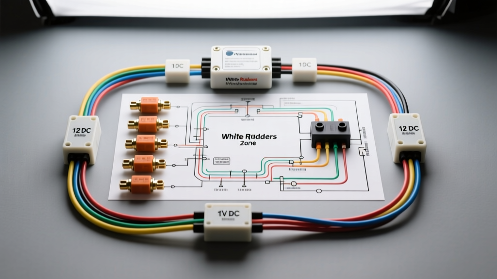
Core Wiring Diagram for White Rodgers Zone Valve (12V DC RV Application)
Because the White-Rodgers 586-series DC solenoid draws up to 2.5A on inrush, wiring it directly to a standard 12V RV digital thermostat (like a Dometic or Webasto timer) will fry the thermostat's internal PCB. You must use an automotive-grade relay to isolate the control circuit from the high-current load circuit.
Schematic Flow & Wire Color Codes (SAE J1128 Standard)
- Power Source (12V+): 14 AWG Red wire from the RV house battery fuse block (10A ATO fuse).
- Ground (12V-): 14 AWG Black wire to a dedicated chassis ground bus bar.
- Control Signal (Thermostat): 18 AWG Blue wire from the thermostat's 'Call for Heat' terminal.
- Load Feed (To Valve): 14 AWG Orange wire from the relay to the valve's positive terminal.
The wiring diagram routes the heavy 14 AWG power directly through a 40A Bosch-style relay. The RV's 12V thermostat only needs to trigger the relay's low-current coil (Pin 86), which requires less than 150mA, keeping the delicate thermostat circuitry safe. For complete wire insulation standards, refer to the SAE J1128 Low Tension Primary Cable specifications to ensure your wire jacket can withstand the under-hood or under-chassis heat of a motorhome.
Step-by-Step Installation & Relay Pinout Guide
To execute the wiring diagram for White Rodgers zone valve setups safely, follow this pinout configuration for a standard ISO mini relay (commonly used in automotive fuse panels and RV distribution boards).
| Relay Pin | Function | Wire Size & Color | Connection Destination |
|---|---|---|---|
| Pin 30 | Common (Power In) | 14 AWG Red | 12V+ Fuse Block (10A Fuse) |
| Pin 87 | Normally Open (Power Out) | 14 AWG Orange | White-Rodgers Valve (+) Terminal |
| Pin 86 | Coil Power (Trigger) | 18 AWG Blue | RV Thermostat 'Call for Heat' Output |
| Pin 85 | Coil Ground | 18 AWG Black | Chassis Ground Bus Bar |
Critical Component: The Flyback Diode
When a DC solenoid valve de-energizes, the collapsing magnetic field generates a massive reverse voltage spike (inductive kickback) that can exceed 100V for a fraction of a millisecond. In a residential home, this is harmless. In an RV's sensitive 12V DC network, this spike can destroy your thermostat, corrupt CAN-bus networks, or fry LED lighting drivers.
Installation Rule: You must solder a 1N4007 flyback diode directly across the White-Rodgers valve terminals. The silver stripe on the diode (cathode) must point toward the positive (12V+) terminal. This creates a closed loop that safely dissipates the inductive spike back into the coil. For more on protecting mobile DC networks, review the RV Industry Association (RVIA) 12V electrical guidelines regarding inductive load suppression.
Troubleshooting Common Mobile Voltage Drops
Even with the correct wiring diagram, White-Rodgers DC solenoids will fail to open if the voltage at the valve drops below 9.5V. Mobile environments suffer from long wire runs and poor ground connections. Use this diagnostic tree to troubleshoot zone valve failures.
Symptom: Thermostat Clicks, Relay Clicks, but Valve Does Not Open
- Cause 1: Severe Voltage Drop. A 20-foot run of 16 AWG wire carrying 2.0A will drop nearly 1.5V. If your house battery is resting at 12.0V, the valve only sees 10.5V, which may be below the cold-cranking threshold of the solenoid.
- Fix: Upgrade the entire positive and negative run to 12 AWG or 10 AWG marine-grade tinned copper wire.
- Cause 2: High-Resistance Ground. Grounding the valve to a painted chassis rail or a rusty frame bolt creates resistance.
- Fix: Use a Deutsch DT-series pigtail connector and route the ground wire back to a dedicated, star-washed copper ground bus tied directly to the battery negative.
- Cause 3: Glycol Contamination on Terminals. Automotive coolant weeping past the valve stem can corrode the spade terminals.
- Fix: Clean terminals with electrical contact cleaner, apply dielectric grease, and seal the connection with dual-wall adhesive-lined heat shrink tubing.
Symptom: Valve Opens, but RV House Battery Drains Rapidly
- Cause: Missing or Blown Hold-Circuit Resistor. Some advanced mobile zone valves utilize a dual-coil system or an internal PWM resistor to drop the holding current from 2.5A to 0.8A after opening. If you are using a standard industrial White-Rodgers continuous-duty solenoid, it will draw maximum current indefinitely.
- Fix: Ensure you have selected a 'Momentary Duty' or 'Low-Power Holding' variant of the 586-series for continuous hydronic routing, or wire an inline power resistor to drop the holding voltage to 9V once the valve is seated.
Final Torque & Crimping Specifications
When terminating the 14 AWG and 18 AWG wires for your White-Rodgers zone valve setup, never use solder alone in high-vibration vehicular environments. Solder wicks into the wire strands, creating a brittle stress point that will snap under chassis vibration. Always use a ratcheting crimp tool (such as the IWISS IWS-16SN) to apply open-barrel or closed-barrel terminals. If connecting directly to the valve's threaded studs, torque the M4 stainless steel nuts to exactly 1.2 Nm (10.6 in-lbs) to prevent cracking the epoxy potting on the solenoid housing while ensuring a vibration-proof electrical bond.
For further technical documentation on Emerson/White-Rodgers solenoid coil specifications and thermal derating curves, consult the Emerson Automation Solenoid Valve Technical Library. Proper selection and wiring of these components will ensure your RV's hydronic heating system operates flawlessly through harsh winters and rugged overland trails.