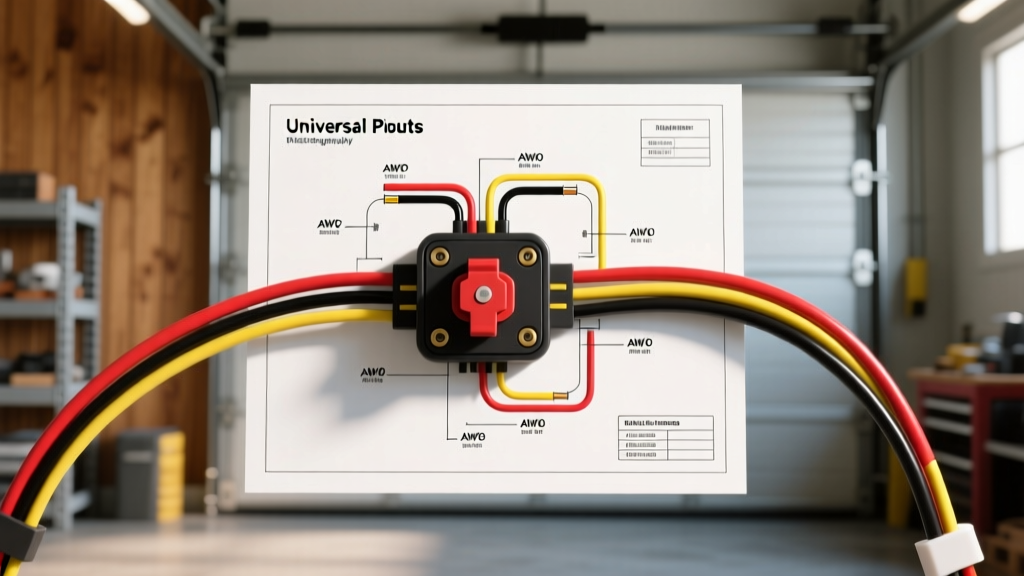
Understanding the Ignition Switch Wiring Diagram
For beginners diving into automotive electrical systems, the ignition switch wiring diagram is the foundational map of a vehicle's power distribution. A common misconception among novice mechanics is confusing the ignition lock cylinder (the mechanical tumbler where you insert the key) with the ignition switch (the multi-position electrical component mounted on the steering column or dash). The lock cylinder merely turns a mechanical actuator rod or gear that physically engages the electrical switch. Understanding how to read the wiring schematic for this switch is critical for diagnosing no-crank conditions, accessory power failures, and parasitic draws.
The Four Universal Switch Positions
Almost all modern and legacy automotive ignition switches operate on a four-position rotary or linear detent system. When you trace a wiring diagram, you will see the internal contacts bridging specific terminals based on these positions:
- OFF (Lock): All primary circuits are open. Only constant battery feeds (like the main B+ terminal) remain live to supply memory to the ECU, radio, and anti-theft modules.
- ACC (Accessory): Powers low-draw convenience items like the radio, power windows, and windshield wipers without energizing the engine management systems.
- ON (Run): The main operating position. This bridges power to the fuel pump, ignition coils, ECU, dashboard gauges, and alternator field.
- START (Crank): Engages the starter solenoid circuit. In many older diagrams, the ACC and sometimes radio circuits are intentionally severed during START to maximize cranking amperage for the starter motor.
Standard Ignition Switch Pinout and Terminal Guide
While OEM connectors vary by manufacturer (e.g., GM's flat rectangular pigtail vs. Ford's multi-cavity harness), the fundamental terminal designations remain consistent across the industry. Below is the standard reference table for a universal 4-terminal ignition switch.
| Terminal ID | Common Label | Function & Load Type | Active Positions |
|---|---|---|---|
| 1 | BAT / B+ | Main Battery Feed (Constant 12V+) | ALL (Always Hot) |
| 2 | ACC | Accessory Circuit (Radio, Wipers) | ACC, ON |
| 3 | IGN / RUN | Ignition & Engine Management | ON, START |
| 4 | ST / SOL | Starter Solenoid Trigger Signal | START (Only) |
Note: Some older vehicles feature a 5th terminal labeled 'I' (Ignition Bypass). This was used to send a full 12V boost to the ignition coil during cranking, bypassing the ballast resistor used in points-style distributors.
Wire Gauge (AWG) and Color Code Standards
When interpreting an ignition switch wiring diagram, wire thickness (AWG) and color coding provide immediate clues about the circuit's purpose. According to the SAE J1128 Standard for low-tension primary automotive cable, wire gauge is dictated by the maximum current draw and the length of the circuit to prevent voltage drop and thermal melting.
Typical AWG Specifications
- BAT Feed (Terminal 1): 8 AWG to 10 AWG. This wire carries the combined amperage of all switched circuits. It is protected by a high-amperage fusible link or a maxi-fuse (40A-60A) at the underhood fuse block.
- IGN & ACC Feeds (Terminals 2 & 3): 12 AWG to 14 AWG. These circuits feed relay coils, the ECU, and the fuse box bus bars. They are typically protected by 15A to 20A fuses.
- START Trigger (Terminal 4): 14 AWG to 16 AWG. Because this wire only triggers a starter relay or solenoid coil (drawing less than 5 amps), heavy gauge wire is unnecessary.
Legacy GM Color Code Reference
General Motors maintained one of the most standardized ignition wiring color palettes from the 1970s through the early 2000s. If you are working on a GM square-body truck or a 90s GM sedan, memorize these colors:
- Red (10 AWG): Constant Battery Feed (BAT)
- Brown (14 AWG): Accessory Feed (ACC)
- Pink (14 AWG): Ignition Feed (IGN/RUN)
- Yellow or Purple (14 AWG): Starter Solenoid Trigger (ST). (Yellow was common in the 70s/80s; Purple became the standard in the 90s).
- Orange (14 AWG): Secondary Accessory (often used for HVAC blower motors).
The Role of the Starter Relay and Neutral Safety Switch
A beginner reading an ignition switch wiring diagram for the first time might wonder why the START terminal wire doesn't lead directly to the starter motor on the engine block. The answer lies in current management. A starter motor can draw 150 to 300 amps under load. Routing 2 AWG battery cables up into the steering column to the ignition switch would be dangerous, expensive, and mechanically rigid.
Instead, the ignition switch sends a low-current 12V signal (usually via a Purple wire) to a Neutral Safety Switch (or clutch interlock switch on manuals). Once the transmission range sensor confirms the vehicle is in Park or Neutral, the signal passes to the Starter Relay in the underhood fuse box. The relay then closes a heavy-duty internal contact, allowing battery power to flow directly to the starter solenoid. For a deeper dive into how these control circuits interact, the AutoShop 101 Electrical Circuits Guide provides excellent foundational schematics.
Step-by-Step Multimeter Troubleshooting
When a vehicle exhibits a 'no-crank' or 'no-power' symptom, use a Digital Multimeter (DMM) to diagnose the switch without immediately replacing parts. Follow this diagnostic tree:
- Verify Constant Power: Set your DMM to DC Volts (20V scale). Back-probe the BAT terminal wire at the switch connector. You should read 12.4V - 12.6V regardless of key position. If you read 0V, you have a broken feed wire or blown fusible link, not a bad switch.
- Test the IGN Circuit: Move the key to the ON (Run) position. Back-probe the Pink (or IGN) wire. You should read battery voltage. If voltage is present here, but the dash is dead, the fault lies downstream (e.g., a blown ignition fuse or bad ground).
- Test the START Circuit: Have an assistant hold the key in the START position. Back-probe the ST wire. You should read 12V+. If you read 12V at the switch, but the starter doesn't engage, the fault is in the neutral safety switch, the starter relay, or the wiring to the solenoid.
- Check for Voltage Drop: If the switch feels hot to the touch or the dash lights dim severely during cranking, perform a voltage drop test across the switch contacts. Place your red probe on the BAT terminal and the black probe on the IGN terminal while the switch is loaded. A reading above 0.2V indicates internal carbon tracking or pitted copper contacts inside the switch. For more advanced diagnostic procedures, refer to AA1Car's Ignition Switch Diagnostics.
Safety Precautions: Airbags and Battery Disconnects
Working on the ignition switch wiring harness requires extreme caution. In vehicles manufactured after 1996 (OBD-II era), the ignition switch is located inches away from the Supplemental Inflatable Restraint (SIR) system, commonly known as the airbag.
- Disconnect the Battery: Always remove the negative battery cable first and isolate it. Wait at least 15 minutes before unplugging any yellow-colored SIR connectors to allow the backup capacitors to discharge.
- Avoid Back-Probing SIR Wires: Never pierce airbag wiring with a multimeter probe. The tiny electrical current from the DMM's internal battery is enough to accidentally deploy the airbag module, causing severe injury.
- Use Proper Terminal Release Tools: Modern ignition switches use weather-pack or micro-pack sealed connectors. Do not pull on the wires to disconnect them; use a plastic terminal pick to depress the locking tangs to prevent damaging the wire crimps.
By mastering the fundamentals of the ignition switch wiring diagram, understanding AWG requirements, and following systematic voltage testing, you can confidently diagnose and repair one of the most critical nodes in your vehicle's electrical architecture.