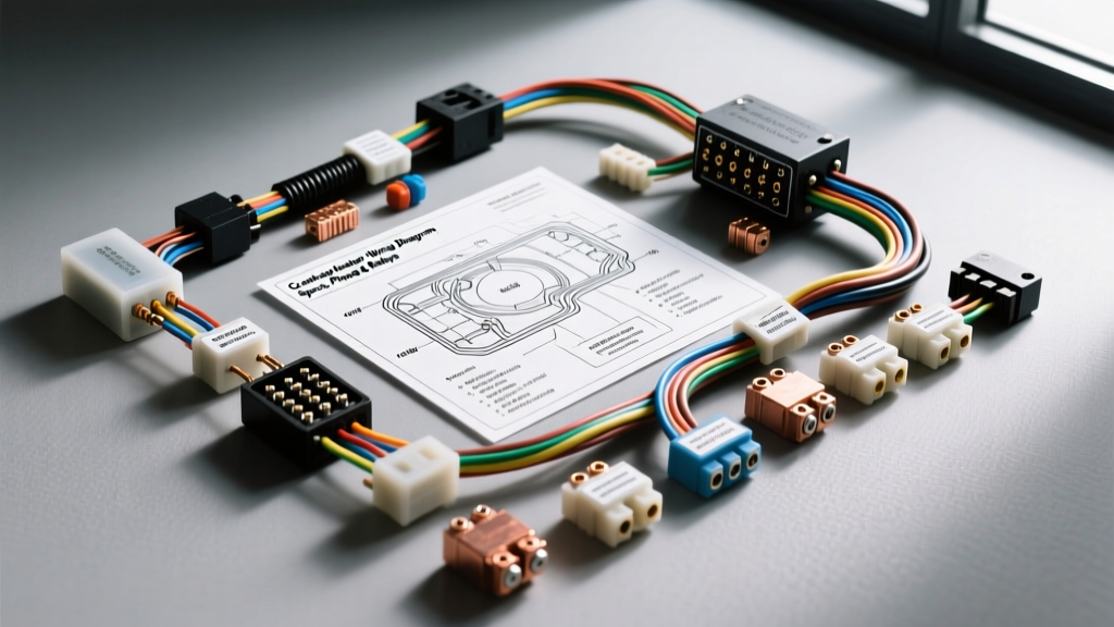
Understanding Crankcase Heater Electrical Architecture
A crankcase heater (often integrated into the oil pan or block heater circuit) is a critical cold-weather component designed to reduce engine oil viscosity, prevent cavitation, and minimize cranking wear during sub-freezing starts. While passenger vehicles typically rely on simple 120V AC block heaters, heavy-duty diesel applications (such as the Cummins 6.7L and Ford 6.7L Powerstroke) and advanced EV/Hybrid thermal management systems utilize complex 12V DC or high-amperage 120V AC crankcase heating elements controlled directly by the Powertrain Control Module (PCM).
This technical specification reference details the crankcase heater wiring diagram, ISO relay pinouts, AWG wire sizing, and PCM control logic required for proper installation, diagnostics, and repair. Adhering to SAE J1292 Automotive Electrical Systems Standards is mandatory when servicing or modifying these high-draw circuits to prevent voltage drop, harness chafing, or parasitic battery drain.
OEM 12V DC Crankcase Heater Wiring Diagram & Circuit Path
In a factory 12V DC cold-weather package, the crankcase heater is not a direct battery connection. It is an electrically isolated, relay-switched circuit monitored by the PCM. The PCM evaluates the Ambient Air Temperature (AAT) sensor and Engine Coolant Temperature (ECT) sensor to determine if the heater should be energized prior to cranking or during a glow-plug/grid-heater cycle.
Circuit Topology
- Power Feed (B+): 12V DC from the Power Distribution Box (PDB) via a high-amperage MAXI or MEGA fuse (typically 30A to 50A).
- Relay Input (Pin 30): 10 AWG wire supplies constant battery voltage to the ISO relay.
- PCM Control (Pins 85/86): The PCM provides a ground-side switch for the relay coil. Pin 86 receives 12V ignition or battery power; Pin 85 is the PCM-controlled ground.
- Relay Output (Pin 87): 10 AWG wire routes power from the relay to the crankcase heating element.
- Element Ground: The heating element grounds directly to the engine block via a dedicated, corrosion-resistant grounding lug, completing the circuit.
ISO 280 Mini Relay Pinout Specifications
The 12V DC crankcase heater circuit relies on a heavy-duty ISO 280 Mini Relay. Using a standard 30A/40A relay is insufficient for continuous cold-weather duty cycles; a 50A or 70A heavy-duty relay with a high-temperature coil rating is required.
| Relay Pin | Designation | Wire Gauge (AWG) | Circuit Function | Multimeter Test (Key Off) |
|---|---|---|---|---|
| 30 | Common (Input) | 10 AWG | Constant B+ from PDB Fuse | 12.6V (Battery Voltage) |
| 85 | Coil Ground | 16 AWG | PCM Ground-Side Driver | Continuity to PCM (when commanded) |
| 86 | Coil Power | 16 AWG | Ignition or B+ Feed to Coil | 12.6V (Ignition ON) |
| 87 | N/O Output | 10 AWG | Power to Crankcase Heater | 12.6V (when relay energized) |
| 87a | N/C Output | N/A | Not Used in Heater Circuit | Continuity to Pin 30 (relay off) |
Wire Gauge (AWG) and Amperage Draw Chart
Sizing the wire correctly is critical. Crankcase heaters draw significant current, and undersized wiring will result in severe voltage drop, reduced heating efficiency, and potential harness fires. The following chart aligns with Bosch Automotive Relay Technical Specifications and standard copper wire ampacity ratings for chassis wiring (12V DC).
| Heater Wattage (12V) | Amperage Draw | Minimum AWG (Up to 5 ft) | Minimum AWG (Up to 10 ft) | Required Fuse Rating |
|---|---|---|---|---|
| 150W | 12.5A | 14 AWG | 12 AWG | 15A (ATO/ATC) |
| 300W | 25.0A | 10 AWG | 10 AWG | 30A (MAXI) |
| 500W | 41.6A | 8 AWG | 6 AWG | 50A (MAXI) |
| 1000W | 83.3A | 4 AWG | 2 AWG | 100A (MEGA) |
120V AC External Crankcase & Block Heater Specifications
For vehicles equipped with external AC shore-power connections, the crankcase heater wiring diagram shifts from DC relay logic to AC thermal management. These systems utilize a 120V AC, 3-prong grounded SJTOW (oil and water-resistant) cord.
AC Circuit Components
- Cord Gauge: Minimum 14 AWG (3-conductor) for heaters up to 1000W; 12 AWG for 1500W+ systems.
- Thermal Cutoff Fuse: Integrated directly into the heating element harness. Rated to blow at 240°C (464°F) to prevent oil combustion in the event of a dry-fire or coolant loss.
- Grounding Ring: The green ground wire must be terminated to a clean, unpainted engine block stud using a star washer to bite through surface corrosion, ensuring a true earth ground.
PCM Control Logic and Thermal Thresholds
Modern PCMs do not allow the 12V crankcase heater to operate continuously, which would drain the starting batteries. The PCM utilizes a localized CAN-bus or hardwired logic gate based on the following parameters:
- Ambient Air Temperature (AAT): The PCM will only permit relay closure if the AAT sensor reads below 36°F (2°C).
- Engine Coolant Temperature (ECT): If the ECT is below 104°F (40°C), the PCM will energize the relay.
- Timer / Duty Cycle: Once the ignition is turned to the 'ON' position (pre-crank), the PCM energizes the relay for a maximum of 15 to 30 seconds to slightly warm the oil pan boundary layer before engaging the starter solenoid.
Diagnostic Troubleshooting: Voltage Drop & Resistance
When diagnosing a 'Crankcase Heater Circuit Malfunction' (often associated with generic OBD-II codes or manufacturer-specific cold-start codes), follow this structured diagnostic path using a digital multimeter (DMM). For advanced waveform analysis, refer to Fluke Automotive Multimeter Diagnostic Guides.
Step 1: Heating Element Resistance Test
Disconnect the heater element connector. Set the DMM to Ohms (Ω). Measure across the two terminals of the heating element.
- Expected Reading (300W 12V Element): ~0.48 Ω
- Expected Reading (500W 12V Element): ~0.28 Ω
- Failure Mode: An 'OL' (Out of Limits) reading indicates an internal open circuit (burned element). A reading of 0.00 Ω indicates a short circuit.
Step 2: Voltage Drop Testing the Power Feed
Do not rely solely on static voltage readings. A wire with 2 strands of copper remaining will still show 12V with no load, but will fail under the 25A+ load of the crankcase heater.
- Connect the DMM red lead to the positive battery terminal and the black lead to the input side of the heater element (Pin 87 side of the harness).
- Command the heater ON via a bidirectional scan tool or by jumping the relay.
- Specification: Maximum allowable voltage drop on the 12V supply side is 0.2V.
- Specification: Maximum allowable voltage drop on the ground side (element ground to battery negative) is 0.1V.
Step 3: Relay Coil and PCM Driver Verification
If the relay does not click, test the coil circuit. Disconnect the relay. Measure resistance across pins 85 and 86. A healthy ISO relay coil should read between 65 Ω and 120 Ω. If the coil is good, use a test light or logic probe on the PCM ground wire (Pin 85 harness side) while the ignition is ON and AAT is below freezing. The PCM should provide a pulsing or solid ground to complete the circuit.
Harness Routing and Environmental Protection
The physical routing of the crankcase heater wiring diagram is just as critical as the electrical specifications. The engine bay environment exposes the harness to extreme heat cycles, vibration, and corrosive road salts.
- Loom Requirements: All 12V DC wiring within 12 inches of the exhaust manifold or turbocharger must be wrapped in high-temperature fiberglass sleeving or TCA (Thermal Control Assembly) loom.
- Connector Sealing: Use heat-shrink butt splices with integral polyamide adhesive liners. Standard vinyl tape will unwrap under engine heat.
- Dielectric Grease: Apply a marine-grade dielectric grease to the heating element connector to prevent galvanic corrosion between the copper harness terminals and the aluminum engine block.
By strictly adhering to these wiring schematics, AWG requirements, and diagnostic procedures, technicians can ensure reliable cold-weather starting, protect the PCM from inductive voltage spikes, and extend the service life of the engine's internal rotating assembly.