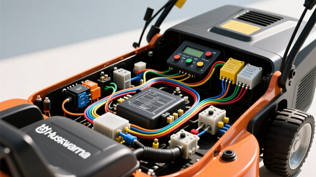
Introduction to Husqvarna Zero Turn Electrical Systems
Modern commercial and residential zero-turn mowers, including the popular Husqvarna MZ, Z200, and TS series, rely on complex 12-volt DC electrical systems to manage engine starting, blade engagement, and operator safety interlocks. When electrical faults occur, guessing can lead to damaged components or unsafe operation. Utilizing a precise wiring diagram for Husqvarna zero turn mower models is the only reliable way to isolate faults in the starting circuit, Power Take-Off (PTO) clutch, and charging system. This guide provides a step-by-step troubleshooting flow designed for automotive and small engine electrical technicians, complete with wire gauge specifications, pinout configurations, and multimeter testing procedures.
Essential Tools for Electrical Diagnostics
Before consulting the schematic, ensure you have the proper diagnostic equipment. Outdoor power equipment is subjected to high vibration, moisture, and extreme temperature fluctuations, which can cause intermittent faults that a simple test light might miss.
- Digital Multimeter (DMM): Must have DC voltage, AC voltage, resistance (Ohms), and continuity testing capabilities with an audible beep.
- Wire Piercer / Back-Probe Pins: For testing connectors without damaging the weather-seals.
- Electrical Contact Cleaner & Dielectric Grease: Essential for restoring corroded AMP Superseal or Delphi Weather-Pack connectors common in mower harnesses.
- OEM Schematic: Always reference the specific wiring diagram for Husqvarna zero turn mower models matching your exact chassis and engine serial number (e.g., Kawasaki FX or Kohler 7000 series).
Step 1: Battery and Main Power Circuit Verification
The foundation of any zero-turn electrical system is the main power delivery. Husqvarna mowers typically utilize a 12V, 230+ CCA (Cold Cranking Amps) U1-sized battery. The main power cable is usually a 10 AWG Red wire routing from the battery positive terminal to the starter solenoid, and then to the main 20A or 30A blade fuse.
Voltage Drop Testing the Main Circuit
Do not just test for 12 volts; test for voltage drop under load. Set your DMM to DC Volts. Place the red probe on the battery positive post and the black probe on the solenoid input terminal. Have an assistant turn the key to the "Start" position. A voltage drop reading greater than 0.2V indicates high resistance, often caused by corrosion inside the ring terminal or a loose battery clamp. Repeat this test on the ground side (10 AWG Black wire) from the engine block to the battery negative terminal. According to SAE J1128 standards for low-tension primary cables, maintaining minimal voltage drop is critical for delivering adequate amperage to the starter motor.
Step 2: Safety Interlock System and Ignition Switch
Husqvarna zero-turn mowers employ a rigorous safety interlock system to prevent the engine from starting unless the parking brakes are engaged, the steering levers are in the neutral park position, and the PTO is disengaged. Furthermore, the engine will shut off if the operator leaves the seat while the PTO is engaged. These switches are typically wired using 18 AWG or 16 AWG wires to handle low-current logic signals.
Ignition Switch Pinout Diagnostics
The ignition switch acts as the central routing hub for the 12V logic. Most Husqvarna models use a standard 5-pin or 6-pin rotary switch. Below is the standard pinout reference used when tracing the wiring diagram for Husqvarna zero turn mower ignition circuits.
| Terminal Pin | Function | Typical Wire Color | State in 'RUN' | State in 'START' |
|---|---|---|---|---|
| B (Battery) | 12V Main Power In | Red (12 AWG) | 12V | 12V |
| S (Starter) | Solenoid Trigger | Yellow or White (14 AWG) | 0V | 12V |
| I (Ignition) | Engine Coil / Fuel Solenoid | Purple or Pink (16 AWG) | 12V | 12V |
| G (Ground) | Magneto Kill (Gas) / Fuel Shutoff (Diesel) | Black or Gray (18 AWG) | Open | Open |
| M (Magneto) | Ignition Coil Ground Path | Black (18 AWG) | Open | Grounded |
| L (Lights/Accessories) | Headlights / Hour Meter | Blue or Brown (16 AWG) | 12V | 0V |
Troubleshooting Tip: If the mower cranks but will not start, check the 'I' terminal. If the engine uses a Kohler or Kawasaki with a fuel shutoff solenoid on the carburetor bowl, it requires 12V at the 'I' terminal to retract the fuel pin. If there is no voltage, trace the 16 AWG Purple wire back through the main harness for a broken connection or blown inline fuse.
Step 3: PTO Clutch and Starter Solenoid Troubleshooting
The Electric PTO (Power Take-Off) clutch is one of the highest-draw components on the mower, often pulling between 12 to 18 Amps when initially engaged. Because of this high inrush current, the wiring diagram for Husqvarna zero turn mower models will show the PTO clutch being fed through a heavy-duty 30A relay, rather than being switched directly by the dashboard PTO switch.
Testing the PTO Clutch Coil
Disconnect the 2-pin AMP Superseal connector at the PTO clutch. Set your DMM to Ohms (Ω). Measure the resistance across the two clutch terminals. A healthy electromagnetic clutch coil should read between 2.0 and 4.0 Ohms. If the reading is infinite (OL), the internal coil wire is broken. If the reading is near zero, the coil is shorted internally, which will immediately blow the main PTO fuse upon engagement.
| PTO Diagnostic Metric | Specification / Expected Value | Failure Mode Symptom |
|---|---|---|
| Coil Resistance | 2.0 Ω - 4.0 Ω | Blown fuse (short) or no engagement (open) |
| Clutch Air Gap | 0.015" - 0.025" | Slipping blades, overheated coil, high amp draw |
| Relay Control Voltage | 11.5V - 12.6V DC | Clicking relay but no clutch engagement |
| Voltage at Clutch Plug | 12.0V+ under load | Voltage drop due to corroded harness connectors |
Expert Insight: Many technicians miss the flyback diode wired in parallel with the PTO clutch coil or integrated into the relay harness. When the magnetic field of the clutch collapses upon disengagement, it creates a massive reverse voltage spike. The diode safely dissipates this spike. If the diode fails shorted, the PTO will blow the fuse instantly. If it fails open, the voltage spike can weld the internal contacts of the PTO relay shut, causing the blades to spin continuously even when the key is off.
Step 4: Charging System and Voltage Regulator
The charging system on a Husqvarna zero turn is driven by the engine's stator (alternator). The stator generates AC voltage, which is converted to DC voltage by the regulator/rectifier to recharge the battery and power the 12V accessories. The stator typically outputs 28V to 35V AC at half throttle, and up to 45V AC at full operating RPM (3600 RPM).
Stator and Regulator Testing Flow
- Test Stator AC Output: Unplug the 2-pin or 3-pin stator connector (usually Yellow or Black/Yellow wires). Start the engine and run at full throttle. Set the DMM to AC Volts. Measure across the stator pins. If you read less than 20V AC, the stator is defective or the flywheel magnets have weakened.
- Test Regulator DC Output: Reconnect the stator. Set the DMM to DC Volts. Measure the center output pin on the regulator/rectifier (typically a Red or White 12 AWG wire) to the engine block ground. At full throttle, you should read between 13.8V and 14.4V DC. Anything above 15V indicates a failed regulator that will boil the battery acid and fry sensitive electronic modules.
For detailed engine-specific charging specifications, always cross-reference the Kohler or Kawasaki engine service manuals, as the stator output varies depending on whether the mower is equipped with a 9-amp or 15-amp charging stator.
Symptom-Cause-Fix Decision Trees
Use these rapid diagnostic trees alongside your wiring diagram for Husqvarna zero turn mower schematics to isolate common field failures.
Tree A: Engine Will Not Crank (Silent or Single Click)
- Symptom: Turn key to START, hear a single click from solenoid, but starter does not spin.
- Test: Check voltage at starter 'S' terminal while cranking.
- Result 1: 12V present at 'S' terminal. Fix: Starter motor is defective or seized. Rebuild or replace starter.
- Result 2: 0V at 'S' terminal. Fix: Solenoid internal contacts are burned. Replace 4-post or 3-post starter solenoid.
- Symptom: Turn key to START, absolutely no sound, dashboard lights may dim.
- Test: Bypass safety switches by jumping the solenoid trigger wire directly to the battery positive.
- Result 1: Engine cranks when jumped. Fix: Fault in safety interlock loop (Seat switch, Brake switch, or PTO switch out of adjustment).
- Result 2: Engine still does not crank. Fix: Check main 20A fuse and 10 AWG battery cables for severe voltage drop or corrosion.
Tree B: PTO Clutch Engages But Slips or Overheats
- Symptom: Blades stop spinning in tall grass, clutch housing is too hot to touch.
- Test: Measure DC voltage at the PTO clutch connector while engaged and under load.
- Result 1: Voltage drops below 11.5V. Fix: Inspect wiring harness for chafing against the frame, or test charging system (stator/regulator) for inadequate amperage output.
- Result 2: Voltage is a steady 12.5V+. Fix: Electrical system is fine. The mechanical air gap on the clutch armature is too wide. Adjust the three perimeter nuts to achieve a 0.020" feel gauge clearance, or replace the worn clutch assembly.
Conclusion and Best Practices
Troubleshooting modern outdoor power equipment requires the same rigor as automotive diagnostics. By systematically following the wiring diagram for Husqvarna zero turn mower electrical systems, verifying wire gauge integrity, and utilizing voltage drop testing over simple continuity checks, you can accurately diagnose and repair complex interlock and PTO faults. Always apply a high-quality dielectric grease to all weather-pack connectors after repair to prevent moisture ingress, which is the leading cause of premature electrical failure in zero-turn mowers. For further reading on primary cable insulation and temperature ratings in high-vibration environments, refer to the official Husqvarna technical support and manual download portal.