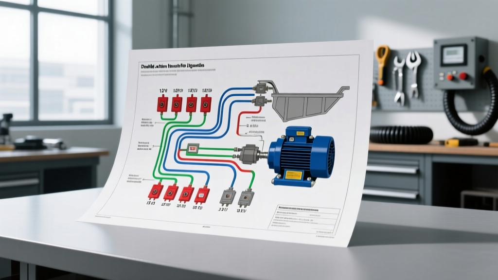
When executing a heavy-duty truck modification—such as installing a custom dump bed, hydraulic liftgate, or snow plow on a Ford F-350 or Ram 3500—integrating a 12V double-acting hydraulic power unit (HPU) is a common but electrically demanding upgrade. Unlike single-acting gravity-return pumps, a double-acting system requires precise electrical control over a 4-way directional valve block to push and pull hydraulic fluid, extending and retracting the cylinder under full pressure.
Most universal HPU kits ship with a generic, poorly translated double acting hydraulic pump wiring diagram PDF. These schematic PDFs often rely on obscure European or Asian electrical symbols that do not align with North American SAE (Society of Automotive Engineers) standards. This guide translates those generic PDF schematics into actionable, vehicle-specific wiring instructions, ensuring your upfit is safe, reliable, and capable of handling the massive inrush currents generated by 1.5 to 2.0 HP hydraulic motors.
Decoding the Generic Wiring Diagram PDF
The factory-included double acting hydraulic pump wiring diagram PDF typically illustrates a direct-wire setup using heavy-duty momentary toggle switches. In a real-world automotive environment, routing 150+ amp cables through the firewall and cab to a toggle switch is a severe fire hazard and violates SAE J1171 electrical safety standards.
Instead of following the PDF's direct-switch schematic, professional upfitters use the PDF solely to identify the solenoid valve block configuration. A standard double-acting HPU features two 12V solenoids on the manifold:
- Solenoid A (Extend/Up): Shifts the internal spool to route high-pressure fluid to the cylinder's base end.
- Solenoid B (Retract/Down): Shifts the spool to route fluid to the rod end, pulling the cylinder back.
Your goal is to trigger these low-amperage solenoid coils (typically drawing 8 to 12 amps each) using OEM upfitter switches and heavy-duty automotive relays, while supplying the main pump motor directly from the battery via a high-amperage Mega fuse.
Heavy-Duty Wiring Specifications and AWG Requirements
Hydraulic pump motors experience extreme inrush current (Locked Rotor Amperage) upon startup, often spiking to 250 amps before settling into a running draw of 120 to 180 amps under load. Undersized wiring will cause severe voltage drop, resulting in sluggish hydraulic operation, melted insulation, or solenoid chatter.
Wire Gauge and Amperage Chart
| Circuit Component | Recommended AWG | Max Continuous Draw | Protection |
|---|---|---|---|
| Main Motor Power (Battery to HPU) | 1/0 AWG or 2/0 AWG | 200A | 250A Mega Fuse |
| Motor Ground (HPU to Chassis/Battery) | 1/0 AWG or 2/0 AWG | 200A | N/A |
| Solenoid A Trigger (Relay to Coil) | 14 AWG (Yellow) | 15A | 15A Mini Fuse |
| Solenoid B Trigger (Relay to Coil) | 14 AWG (Blue) | 15A | 15A Mini Fuse |
| Upfitter Switch Signal (Cab to Relay) | 18 AWG | 3A | OEM Protected |
Relay Integration and OEM Upfitter Switch Pinouts
To properly wire the system, discard the PDF's cab-mounted toggle switch instructions. Instead, utilize the truck's factory upfitter circuits. For example, the Ford F-Series Super Duty features six auxiliary upfitter switches (S1-S6) located on the overhead console, providing switched 12V+ signals via blunt-cut wires under the hood near the brake master cylinder.
Standard Bosch-Style 5-Pin Relay Wiring
You will need two 40A SPDT (Single Pole Double Throw) automotive relays—one for Solenoid A and one for Solenoid B.
- Pin 30 (Common): Connect to a fused 12V+ constant power source (e.g., the load side of the main battery distribution block) using 10 AWG red wire.
- Pin 87 (Normally Open): Connect to the positive terminal of the respective hydraulic solenoid (A or B) using 14 AWG wire.
- Pin 86 (Coil Power): Connect to the OEM Upfitter Switch auxiliary power lead (e.g., Upfitter Switch #1 for 'Dump/Extend').
- Pin 85 (Coil Ground): Connect to a clean, bare-metal chassis ground using 14 AWG black wire.
- Pin 87a (Normally Closed): Not used in this application. Cap with adhesive heat-shrink.
Solenoid Grounding Strategy
The generic PDF often shows the solenoids grounding directly to the pump motor casing or the hydraulic manifold. Do not do this. The painted surfaces and Teflon thread sealant on hydraulic manifolds create high-resistance connections. Run a dedicated 10 AWG ground wire from the negative terminal of each solenoid to a verified, sanded chassis ground point, securing it with a star washer and torquing to 15 lb-ft.
Selecting Terminals and Environmental Sealing
Because HPUs are typically mounted on the exterior frame rail, they are exposed to road salt, water, and vibration. Standard stamped brass terminals will corrode and fail within a single winter season.
- High-Amperage Connections: Use heavy-duty, tinned copper ring terminals for the 1/0 AWG wire. Crimp using a hydraulic crimper, then seal the connection with dual-wall, adhesive-lined marine-grade heat shrink.
- Solenoid Connections: Most directional valves use 1/4-inch spade connectors. Replace cheap vinyl boot covers with Deutsch DT series 2-pin connectors potted with dielectric grease to ensure a watertight seal against pressure washing and road spray.
Step-by-Step Installation and Routing
- Mount the Mega Fuse: Install a 250A Mega fuse holder within 18 inches of the positive battery terminal. This is critical to prevent an un-fused short circuit in the event of a front-end collision.
- Run the 1/0 AWG Cables: Route the main power and ground cables away from exhaust manifolds and sharp frame edges. Use split-loom tubing and secure with UV-resistant zip ties every 12 inches.
- Connect the Solenoids: Attach the 14 AWG trigger wires to the solenoid spade connectors. Ensure the wiring harness has a drip loop before entering any protective conduit to prevent water ingress.
- Test the Directional Valve: Before connecting the hydraulic hoses to the cylinder, activate the upfitter switches to verify the spool shifts audibly (a distinct 'click') and that fluid flows to the correct ports.
- Bleed the System: Cycle the cylinder fully extend and retract 5-6 times without a load to purge air from the lines, checking the reservoir fluid level to prevent pump cavitation.
Troubleshooting Common Hydraulic Electrical Failures
Even with a perfect interpretation of the double acting hydraulic pump wiring diagram PDF, environmental factors can cause system failures. Use this diagnostic tree to resolve common issues:
Symptom: Motor Hums but Cylinder Does Not Move
- Cause 1: Voltage drop across the solenoid coil. If the trigger wire is too long or undersized, the solenoid may not receive the 11.5V minimum required to fully shift the spool against the hydraulic pressure.
- Cause 2: Poor motor ground. Measure voltage between the motor casing and the battery negative terminal while under load. If it reads above 0.5V, clean and retorque the ground connection.
Symptom: Solenoid Chatters Rapidly
- Cause: Insufficient amperage from the trigger source. If you bypassed the relays and wired an OEM upfitter switch directly to the solenoid (ignoring the PDF's relay recommendation), the 3A-5A switch limit is starving the 10A solenoid coil. Always use a 40A relay as an intermediary.
Symptom: Cylinder Drifts Down When Off
- Cause: This is typically a hydraulic failure (leaking internal spool O-rings or a failed pilot-operated check valve), not an electrical one. However, verify that the solenoid is fully de-energizing. A stuck relay (welded Pin 30 to 87) will keep the solenoid partially engaged, bypassing the check valve and allowing fluid to return to the tank.
Authoritative References and Standards
For further technical validation on heavy-duty upfits, consult the following resources:
- Ford Body Builders Layout Book - Essential for locating OEM upfitter switch circuits and understanding factory relay integration on Super Duty chassis.
- SAE J1171 Standard - Marine and heavy-duty automotive electrical standards regarding circuit protection, fuse placement, and environmental sealing.
- MTE Hydraulics Installation Guides - Manufacturer-specific schematics and torque specifications for 12V DC hydraulic power units and directional control valves.