Integrating Residential Controls into Vehicle Electrical Systems
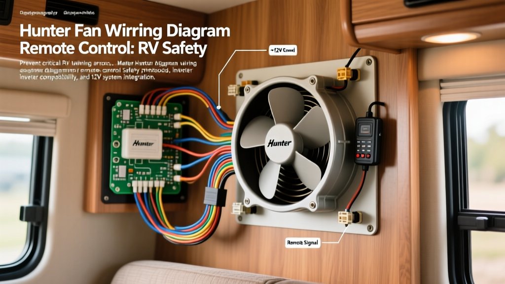
The crossover between residential comfort and automotive electrical engineering has created a massive trend in the RV, skoolie, and overland camper communities. Enthusiasts frequently install residential ceiling fans to improve air circulation in confined vehicle cabins. However, while a standard residential hunter fan wiring diagram remote control schematic assumes a stable 120V AC grid, adapting this system to a vehicle's DC-to-AC inverter network or using it to trigger 12V DC automotive HVAC blowers introduces severe safety and compatibility challenges.
As an automotive electrical specialist, I have diagnosed numerous electrical fires and component failures resulting from improper integration of residential remote receivers into mobile environments. This guide details the critical safety warnings, inverter topology requirements, and advanced 12V DC relay adaptations necessary to safely wire a Hunter remote receiver in a vehicle platform.
Critical Safety Warnings: Inverter Topology & Fire Risks
The most common and dangerous mistake in RV and camper van builds is powering a Hunter remote control receiver with a Modified Sine Wave (MSW) inverter. The Hunter receiver module relies on solid-state switching components, specifically TRIACs (Triode for Alternating Current), to regulate fan speeds and dim lighting.
The Modified Sine Wave Catastrophe
TRIACs require a clean, zero-crossing AC waveform to trigger and commutate properly. An MSW inverter produces a choppy, stepped waveform that lacks smooth zero-crossing points. When a Hunter receiver is fed MSW power, the internal TRIACs fail to switch off correctly, causing them to remain in a high-resistance state. This generates immense localized heat. In a vehicle's enclosed ceiling canopy—often surrounded by combustible insulation materials like Thinsulate or closed-cell spray foam—this thermal runaway frequently leads to melted wire insulation, arcing, and catastrophic canopy fires.
- Solution: You must exclusively use a Pure Sine Wave (PSW) inverter (Total Harmonic Distortion < 5%) to power the Hunter receiver module.
- Wire Sizing: The 120V AC branch circuit feeding the canopy must utilize a minimum of 14 AWG THHN/MTW stranded wire, protected by a 15A AC breaker at the inverter's distribution panel.
Grounding: AC Earth vs. DC Chassis
A fatal wiring error occurs when builders confuse the 12V DC vehicle chassis ground with the 120V AC safety ground. The Hunter receiver's Green wire is an AC safety ground. According to NFPA 1192 (Standard on Recreational Vehicles), the AC safety ground must be tied directly to the inverter's AC grounding bus, which is bonded to the vehicle chassis at exactly one central point (the neutral-to-ground bond). Tying the Hunter receiver's green wire to a random sheet metal screw on the vehicle roof creates a parallel ground path, risking lethal chassis energization if the inverter's internal fault protection trips.
The Resto-Mod HVAC Hack: Controlling 12V DC Blowers
Beyond RV ceiling fans, advanced custom car builders (such as those restoring 1970s C10 trucks or building 1980s resto-mods) utilize the Hunter remote receiver to wirelessly control high-amperage 12V DC automotive blower motors (e.g., Vintage Air or Spal units) hidden behind dash panels. Because the Hunter receiver outputs 120V AC on its load wires, it cannot directly drive a 12V DC motor. Attempting to do so will instantly destroy the receiver and potentially damage the vehicle's ECU via voltage backfeed.
Solid State Relay (SSR) Integration
To safely bridge the 120V AC remote receiver output to a 12V DC automotive blower motor, you must use an automotive-grade Solid State Relay (SSR) or a heavy-duty electromechanical relay. The Hunter receiver's Blue wire (fan load) or White wire (light/load) is used as the 120V AC trigger signal for the relay coil.
- Trigger Circuit: Connect the Hunter Blue wire to Pin 85 of a 120V AC coil Bosch-style relay (or the input side of a 120V AC Crydom SSR).
- AC Return: Connect Pin 86 to the Inverter's AC Neutral/Earth bus.
- DC High-Amperage Circuit: Run 10 AWG primary wire from the vehicle's 12V battery positive terminal, through a 40A inline ANL fuse, to Pin 30 of a secondary 12V DC 40A automotive relay.
- Load Output: Connect Pin 87 of the 12V DC relay to the positive terminal of the Spal/Vintage Air blower motor.
- Motor Ground: Ground the blower motor directly to the vehicle chassis using a minimum 10 AWG ring terminal, torqued to 12 Nm on a clean, bare-metal surface.
Note: When adapting AC dimming signals to DC motors, standard relays will only provide ON/OFF functionality. To achieve variable DC blower speeds using the Hunter remote's dimming circuit, you must implement a 120V AC-to-DC PWM (Pulse Width Modulation) converter module between the receiver and the 12V DC motor.
Hunter Receiver to Vehicle Inverter Wiring Matrix
The following table provides the exact pinout and wire color mapping for integrating the Hunter canopy receiver into an RV's Pure Sine Wave inverter system.
| Hunter Receiver Wire | Wire Color | Vehicle / Inverter Connection Point | AWG & Connector Spec |
|---|---|---|---|
| AC Line In (Hot) | Black | Inverter AC Breaker Panel (15A) | 14 AWG, Wago 221 Lever Nut |
| AC Neutral In | White | Inverter AC Neutral Bus Bar | 14 AWG, Wago 221 Lever Nut |
| AC Safety Ground | Green | Inverter AC Earth Ground Bus | 14 AWG, Ring Terminal (Crimped) |
| Fan Load Out | Blue | Fan Motor Hot (or SSR Trigger) | 14 AWG, Heat Shrink Splice |
| Light Load Out | White (w/ Blue Stripe) | LED Driver Hot (or SSR Trigger) | 16 AWG, Heat Shrink Splice |
| Common Load Return | White (w/ Black Stripe) | Fan/Light Neutral Return | 14 AWG, Wago 221 Lever Nut |
Troubleshooting: RF Interference & Alternator Whine
Vehicle environments are electrically noisy. The alternator, ignition coils, and DC-DC chargers generate massive amounts of Electromagnetic Interference (EMI). Hunter remote controls typically operate on the 315 MHz or 433 MHz RF bands. A common symptom in vehicle installations is a severely reduced remote range (e.g., the remote only works when standing within 2 feet of the canopy).
Diagnosing Signal Degradation
- Antenna Placement: The Hunter receiver features a thin, flexible wire antenna. Do not bundle this antenna with 120V AC wiring or 12V DC power cables. Route it away from the vehicle's A-pillar and headliner metal framing, which acts as a Faraday cage. Tape the antenna flat against a non-metallic interior trim panel using foam tape.
- Alternator Noise Filtering: If the remote pairing sequence fails while the vehicle engine is running, EMI from the alternator's diode bridge is likely drowning out the RF signal. Install a ferrite choke core on the 12V DC power feed leading to the inverter, and ensure the inverter's DC input cables are twisted or kept at least 6 inches away from any low-voltage signal wires.
- DIP Switch Verification: Ensure the DIP switches on both the handheld remote and the canopy receiver match exactly. In dense RV parks or overland campsites, neighboring rigs using identical remote frequencies can cause 'ghost' activations. Always change the factory default DIP switch configuration to a unique binary sequence during installation.
Adherence to Automotive & RV Standards
When modifying a vehicle's electrical system to accommodate residential components, adherence to established safety standards is non-negotiable. All 12V DC high-current connections must comply with SAE J1171 standards for ignition protection and marine/RV environments, utilizing marine-grade tinned copper wire (to prevent galvanic corrosion from vehicle humidity) and adhesive-lined heat shrink terminals. For all 120V AC inverter branch circuits, builders must reference NFPA 1192 guidelines regarding overcurrent protection and wire routing through vehicle bulkheads, ensuring rubber grommets are used wherever wiring passes through sheet metal to prevent insulation chafing and subsequent short circuits.
By respecting the fundamental differences between residential grid power and mobile inverter topology, you can safely integrate advanced remote control conveniences into your vehicle without compromising electrical safety or reliability.