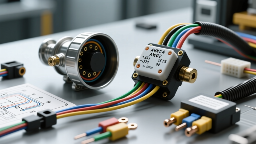
Beyond the Box: The True Cost of Air Horn Wiring
When purchasing a heavy-duty air horn kit—whether it is a Nathan AirChime, Kleinn, or Viair system—the manufacturer provides a basic air horn wiring diagram and a handful of subpar electrical consumables. Relying on the included 16 AWG wire and cheap vinyl crimp connectors is a fast track to voltage drop, thermal compressor failure, and potentially a damaged Body Control Module (BCM). A proper installation requires a comprehensive cost and tool requirements analysis to ensure the high-current demands of an air compressor and the inductive loads of an air solenoid are managed safely.
This guide breaks down the exact wiring architecture for a tank-mounted air horn system, the specialized tools required for aerospace-grade under-hood connections, and a realistic budget for the electrical consumables that separate a professional install from an amateur fire hazard.
System Architecture: Tank & Pressure Switch vs. Direct Drive
Before analyzing costs, we must define the wiring topology. True train horn systems utilize an onboard air tank. This requires splitting the electrical system into two isolated circuits:
- Circuit A (Compressor Management): Wired through a mechanical pressure switch (e.g., 110 PSI on / 145 PSI off). The compressor runs independently of the horn button to maintain tank pressure.
- Circuit B (Solenoid Trigger): Activated by the vehicle’s factory horn button, triggering the 12V air valve solenoid to release air through the trumpets.
Direct-drive systems (no tank) wire the compressor and solenoid in parallel through a single heavy-duty relay. While cheaper, this subjects the compressor motor to massive startup surges every time the horn is tapped, drastically reducing motor brush life. We will focus on the industry-standard tank-mounted pressure switch topology, as dictated by Viair Corporation Technical Resources.
The Air Horn Wiring Diagram: Pinouts & Circuit Logic
A standard Bosch-style 4-pin Mini ISO relay is the heart of the solenoid trigger circuit. Below is the definitive pinout configuration for isolating the factory horn trigger from the high-draw air solenoid.
Relay Pinout Specification (Bosch / TE Connectivity Standard)
| Pin Number | Circuit Function | Wire Gauge (AWG) | Connection Point |
|---|---|---|---|
| 30 | High-Current 12V+ Input | 12 AWG | Vehicle Battery (+) via 20A Inline Fuse |
| 87 | High-Current 12V+ Output | 14 AWG | Air Valve Solenoid (+) Terminal |
| 86 | Low-Current Trigger Input | 18 AWG | Factory Horn Wire (or BCM Interface Module) |
| 85 | Relay Coil Ground | 16 AWG | Clean Chassis Ground (Bare Metal) |
Compressor & Pressure Switch Circuit
The compressor circuit bypasses the relay entirely to prevent the relay contacts from arcing under the compressor's 30-amp startup surge. Instead, power flows from the battery through a 40A ANL fuse, into the SAE J1128 compliant 10 AWG primary cable, through the pressure switch, and directly to the compressor motor positive terminal. The compressor negative terminal is grounded directly to the chassis or battery negative using a minimum 8 AWG ground strap to minimize voltage drop.
Modern Vehicle Integration: The BCM Threat
The most critical failure point in modern air horn installs (2015+ Ford, GM, and Ram trucks) is the horn trigger wire. Modern vehicles do not send raw 12V+ battery power to the horn; they use multiplexed LIN/CAN bus signals or low-current BCM outputs rated for a maximum of 2 to 5 amps.
Tapping a standard relay coil (Pin 86) directly into a modern BCM horn output can cause two catastrophic failures:
- Overcurrent Damage: The relay coil draws roughly 150mA-300mA, which may exceed the BCM's solid-state switch limit, frying the internal transistor.
- Inductive Kickback: When the relay de-energizes, the collapsing magnetic field sends a high-voltage spike back into the BCM, causing permanent logic board damage.
The Solution: You must budget for a high-impedance trigger interface module (such as the PAC TR-4 or a diode-isolated optocoupler). This module senses the factory signal voltage without drawing significant current, and safely triggers your aftermarket relay using an isolated 12V source.
Tool Requirements Analysis: Achieving Aerospace-Grade Connections
Under-hood environments subject wiring to extreme thermal cycling, moisture, and corrosive road salts. The tools you use dictate the longevity of the install. Discard the cheap vinyl crimpers included in auto parts store kits.
Essential Tooling Checklist
- Ratcheting Terminal Crimper: Required for non-insulated or heavy-gauge insulated terminals. A ratcheting tool ensures the exact deformation profile required for a gas-tight mechanical bond, preventing moisture ingress and oxidation.
- Precision Wire Strippers: Tools like the Knipex MultiStripper prevent nicking the outer strands of Oxygen-Free Copper (OFC) wire. Nicked strands reduce the effective AWG and create localized resistance hotspots.
- Digital Multimeter (DMM): Essential for verifying the factory horn trigger signal type (12V+ vs. Multiplexed Ground-Switched) and testing for voltage drop across the pressure switch and ground straps.
- Heat Gun & Polyolefin Tubing: Marine-grade adhesive heat shrink (3:1 shrink ratio with internal meltable sealant) is mandatory. Standard PVC heat shrink will crack under engine bay vibrations and allow capillary action to draw water into the copper strands.
Component & Cost Breakdown: Budgeting the Hidden Consumables
The $250 price tag on an air horn kit rarely covers the high-grade electrical consumables required for a safe install. Below is a realistic cost analysis for the wiring components necessary to meet TE Connectivity automotive relay standards and SAE wiring guidelines.
| Component Category | Specification / Requirement | Est. Cost (USD) | Why It Matters |
|---|---|---|---|
| Primary Power Wire | 10 AWG OFC (Oxygen-Free Copper), Tinned | $35.00 | Prevents voltage drop during 30A compressor startup surges. Tinning prevents galvanic corrosion. |
| Trigger & Relay Wire | 14/16 AWG GXL Cross-Linked Polyethylene | $18.00 | GXL insulation withstands 125°C, resisting melting against exhaust headers or engine blocks. |
| Overcurrent Protection | 40A ANL Fuse + Marine Fuse Holder | $22.00 | ANL fuses handle high inrush currents without nuisance blowing, unlike standard AGC glass fuses. |
| BCM Interface Module | PAC TR-4 or Equivalent Optocoupler | $25.00 | Mandatory for 2015+ vehicles to protect the factory Body Control Module from inductive kickback. |
| Terminals & Heat Shrink | Adhesive-Lined Ring Terminals, 3:1 Polyolefin | $28.00 | Adhesive sealant creates a waterproof barrier, preventing green rot (copper oxidation). |
| Heavy Duty Relay | 40A Bosch-Style Mini ISO (with Diode) | $12.00 | Internal suppression diode protects the trigger switch from voltage spikes. |
| Total Consumables | Professional-Grade Wiring Budget | $140.00 | Excludes the cost of the horn kit, compressor, and air tank. |
Wire Gauge (AWG) & Voltage Drop Mathematics
A common mistake in air horn wiring is using 14 AWG wire for the compressor motor. While a compressor running at 15 amps might technically operate on 14 AWG wire, it ignores the physics of voltage drop and startup inrush current.
According to Ohm's Law and standard copper resistance tables, 10 feet of 14 AWG copper wire (20 feet round trip) has a resistance of approximately 0.051 ohms. During a compressor startup surge of 35 amps, the voltage drop is calculated as:
V = I × R (35A × 0.051Ω = 1.78 Volts Dropped)
If your alternator is outputting 13.8V, the compressor motor only sees 12.02V at startup. As the wire heats up in the engine bay, resistance increases, dropping the voltage further. Low voltage causes the compressor motor to draw more amperage to maintain wattage output, leading to thermal overload, melted internal windings, and premature failure. Upgrading to 10 AWG wire drops the resistance to 0.020 ohms, reducing the startup voltage drop to a negligible 0.70V, ensuring maximum motor torque and longevity.
Real-World Troubleshooting & Failure Modes
Even with a perfect diagram, environmental factors can introduce faults. Use this decision tree to diagnose common air horn electrical failures:
- Symptom: Relay "Chatters" Rapidly When Horn Button is Pressed.
Cause: Voltage drop on the trigger circuit (Pin 86) or a poor ground on Pin 85. The relay pulls in, the voltage sags, the relay drops out, voltage recovers, and the cycle repeats.
Fix: Clean the chassis ground contact point down to bare metal and apply dielectric grease. Verify the trigger wire is not sharing a ground path with high-draw accessories. - Symptom: Compressor Runs Continuously and Will Not Shut Off.
Cause: Pressure switch contacts have welded together due to arcing, or the pressure switch port is clogged with moisture/debris, preventing the diaphragm from sensing tank pressure.
Fix: Disconnect power immediately. Replace the pressure switch and install a small inline air filter on the switch port to prevent moisture ingress. - Symptom: Horn Sounds Weak or "Sputters".
Cause: This is rarely an electrical fault. It is almost always a plumbing restriction or moisture in the air lines freezing/corroding the solenoid valve diaphragm.
Fix: Verify the air line diameter matches the solenoid port (do not step down from 1/2" to 1/4" tubing). Ensure the air tank is drained regularly to prevent internal rust from jamming the valve.
Final Installation Directives
Executing a heavy-duty air horn wiring diagram requires treating the vehicle's electrical system with the same respect as a factory OEM harness. By budgeting for OFC copper wire, ratcheting crimp tools, adhesive heat shrink, and BCM-safe interface modules, you eliminate the primary points of failure associated with aftermarket 12V accessories. Always route wiring away from exhaust manifolds and steering shafts, secure looms every 12 inches with UV-resistant zip ties or P-clips, and verify all connections with a digital multimeter before applying power.