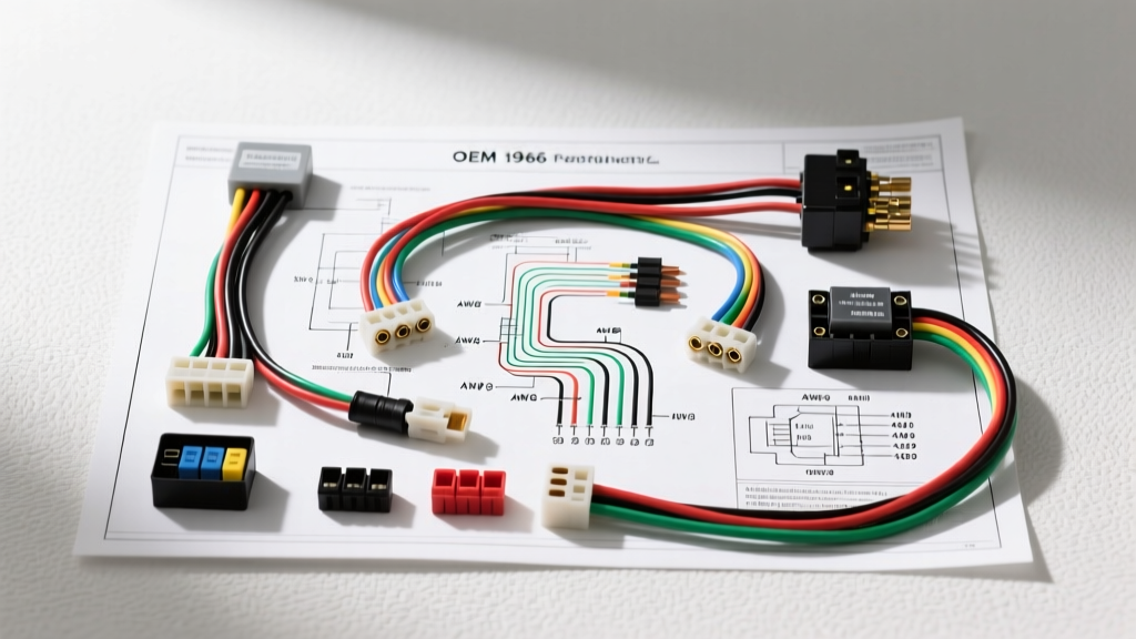
Introduction to the 1966 Mustang Electrical Architecture
The 1966 Ford Mustang represents a pivotal year in classic automotive electrical design. Operating on a 12-volt, negative-ground system, the 1966 model year bridged the gap between early 1960s generator-based charging systems and modern alternator setups. Unlike modern vehicles that rely on multiplexed CAN-bus networks and centralized power distribution modules, the 1966 Mustang utilizes a decentralized, point-to-point wiring architecture. Power is routed directly from the battery to the fender-mounted starter solenoid, which acts as the primary power distribution node for the entire vehicle.
For restoration specialists and diagnostic technicians, understanding the exact OEM wire color codes, American Wire Gauge (AWG) specifications, and connector types is critical. The factory wiring harness utilizes Packard Electric bullet connectors, standard 1/4-inch spade terminals, and cloth-braided or early PVC-insulated copper wire. This technical reference provides the exact specifications required to diagnose, repair, or completely rewire a first-generation Mustang.
Primary Power Distribution & AWG Specifications
The main power feed originates at the battery and routes to the fender-mounted starter solenoid. From the solenoid, the harness branches into the main dash harness, the lighting harness, and the engine feed. The following table outlines the critical high-amperage circuits that require strict adherence to AWG sizing to prevent voltage drop and thermal failure.
| Circuit Description | AWG Size | OEM Color Code | Routing & Function |
|---|---|---|---|
| Battery to Solenoid (B+) | 1 AWG (V8) / 2 AWG (I6) | Black | Positive battery cable; supplies main bus. |
| Solenoid to Ammeter | 10 AWG | Yellow (Y) | Routes through the dash ammeter gauge. |
| Ammeter to Main Harness | 10 AWG | Yellow w/ Black Stripe (Y-BK) | Feeds the headlight switch and ignition switch. |
| Solenoid to Alternator/Gen | 10 AWG | Yellow (Y) | Direct charge wire to the battery side of the system. |
| Ignition Switch to Coil | 16 AWG (Resistance) | Pink (P) | Provides reduced voltage to the ignition coil. |
The Fender-Mounted Starter Solenoid Node
The starter solenoid on the 1966 Mustang is a 4-post electromagnetic switch. It is crucial for troubleshooting no-crank conditions. The posts are designated as follows:
- B (Battery): Receives constant 12V+ from the battery via the heavy 1 AWG cable.
- M (Motor): Outputs 12V+ to the starter motor only during cranking (Black/Yellow stripe, 4 AWG).
- S (Start): Receives the trigger signal from the ignition switch (Red/Blue stripe, 14 AWG) when the key is in the 'START' position.
- I (Ignition Bypass): Outputs a full 12V+ bypass signal directly to the ignition coil (Brown/White stripe, 14 AWG) during cranking to compensate for voltage drop across the starter circuit.
The 1966 Charging System: Generator vs. Alternator Transition
One of the most complex aspects of the 1966 Mustang wiring diagram is the mid-year transition from the Autolite generator to the Autolite alternator. Early production models, inline-6 cylinders, and standard V8s were equipped with the 3-post generator and a corresponding 3-terminal mechanical voltage regulator. Late-production models, high-performance V8s, and Shelby GT350s received the 1-wire or 3-wire alternator with a 4-terminal regulator.
Voltage Regulator Pinout & Wiring Specifications
| Regulator Terminal | Generator System (3-Post) | Alternator System (4-Post) | Wire Color & AWG |
|---|---|---|---|
| BAT | 12V+ Sensing Feed | 12V+ Sensing Feed | Yellow (Y), 14 AWG |
| ARM | Armature Output from Gen | Not Used (Jumper to BAT) | Orange (O), 14 AWG |
| FLD | Field Coil Control | Field Coil Control | Green (G), 14 AWG |
| S (Stator) | Not Used | Stator Signal from Alt | White (W), 14 AWG |
Diagnostic Note: If a 1966 Mustang has been retrofitted with a modern 1-wire internally regulated alternator (such as a Powermaster or Ford 3G swap), the external voltage regulator must be bypassed. The original Green (FLD) wire should be capped, and the alternator BAT terminal must be wired directly to the battery side of the starter solenoid using a minimum of 8 AWG wire to handle modern 100A+ output.
Lighting, Turn Signals, and Dash Accessories
The 1966 Mustang does not utilize a centralized fuse block for high-draw lighting circuits. Instead, the headlight switch contains an internal thermal circuit breaker that protects the headlight and parking light circuits. The under-dash fuse block, located on the driver's side kick panel, contains only 4 to 5 glass tube fuses (typically 14A or 20A) protecting low-draw accessories like the radio, wipers, heater blower, and cigar lighter.
| Lighting Circuit | OEM Wire Color | AWG | Connector Type |
|---|---|---|---|
| Headlights (High Beam) | Red w/ Black Stripe | 14 AWG | 3-Pin Sealed Beam Plug |
| Headlights (Low Beam) | Green w/ Black Stripe | 14 AWG | 3-Pin Sealed Beam Plug |
| Parking / Marker Lights | Brown (Br) | 16 AWG | Single Bullet Connector |
| Tail / Stop Lights | Brown (Br) / Green (G) | 14 AWG | 1157 Bayonet Socket Pigtail |
| Turn Signal (Front) | White w/ Blue Stripe | 16 AWG | Single Bullet Connector |
| Turn Signal (Rear) | Green w/ Orange Stripe | 16 AWG | 1157 Bayonet Socket Pigtail |
Critical Troubleshooting: The Pink Resistance Wire
One of the most common failure points and restoration errors in the 1966 Mustang wiring diagram involves the ignition coil feed wire. The wire routing from the ignition switch 'ON' terminal to the positive terminal of the ignition coil is a Pink (P) 16 AWG resistance wire.
This wire is engineered to have approximately 1.35 ohms of resistance. Its purpose is to drop the system voltage from 14.2V (charging voltage) down to roughly 9V-10V at the coil during normal operation. This prevents the Autolite single-wire distributor points from arcing and burning out prematurely, and prevents the ignition coil from saturating and overheating.
Real-World Failure Mode: Many amateur restorers mistakenly cut out the brittle, cloth-covered pink wire and replace it with standard 14 AWG copper wire. While the car will start, the lack of resistance will cause full system voltage to hit the coil. This results in melted point contacts within 500 miles, a swollen ignition coil, and erratic misfires at high RPM. If the original pink resistance wire is broken, it must be replaced with a modern ballast resistor wire or a ceramic 1.5-ohm ballast resistor spliced into a standard copper feed.
Unibody Grounding & Real-World Failure Modes
Unlike body-on-frame trucks of the same era, the 1966 Mustang utilizes a unibody chassis. The electrical system relies heavily on the sheet metal body and engine block to complete return circuits to the battery. Over 50 years, rust, polyurethane paint, and powder-coated engine brackets severely compromise these ground paths.
Mandatory Ground Strap Locations
- Engine Block to Firewall: A heavy braided 4 AWG ground strap must connect the rear of the intake manifold or cylinder head to the firewall. Without this, the starter motor will attempt to ground through the throttle linkage or heater control cables, melting them instantly.
- Alternator/Generator Bracket: The charging system grounds through the cast-iron mounting bracket. The mating surfaces between the alternator case, the bracket, and the engine block must be bare metal. Use a star washer to bite through corrosion and paint.
- Headlight Harness Ground: The front lighting harness grounds via a ring terminal secured to the inner fender apron near the voltage regulator. If this connection is painted over during bodywork, the headlights will back-feed through the high-beam indicator light on the dash, causing a 'ghosting' effect where all four headlights dimly glow regardless of the switch position.
Authoritative References & Standards
When performing a complete harness restoration or diagnosing complex parasitic draws, always cross-reference your work with factory documentation and established electrical standards:
- SAE International J1128 Standard - Guidelines for low-tension primary battery cable specifications, insulation temperature ratings, and AWG current-carrying capacities in automotive applications.
- Mustang Club of America (MCA) Restoration Guidelines - The definitive authority on OEM wire color codes, cloth-braided harness routing, and correct date-coded voltage regulator specifications for concours-level 1966 Mustang restorations.
- Ford Service Content Delivery Network - Archival access to original Ford Motor Company shop manuals, including the 1966 Mustang electrical troubleshooting flowcharts and generator bench-testing procedures.