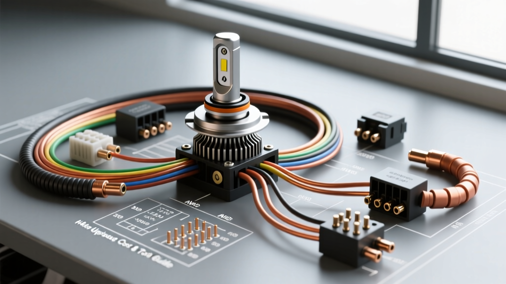
The Electrical Reality of H4 (9003/HB2) Headlight Circuits
The H4 headlight bulb, commonly known in the North American market as the 9003 or HB2 dual-filament halogen lamp, is a staple in global automotive lighting. However, when enthusiasts and technicians search for an H4 headlight wiring diagram, they are rarely looking to replicate the factory harness. Instead, they are seeking to bypass it. Factory headlight wiring in vehicles equipped with H4 bulbs—ranging from 1990s Japanese imports to classic European sedans—frequently relies on 18 AWG or 16 AWG wire routed through the steering column switch and aging bulkhead connectors.
Halogen bulbs are extraordinarily sensitive to voltage drop. According to automotive lighting engineering standards, a mere 5% reduction in voltage at the bulb terminal results in an approximate 15% loss in luminous flux (light output). When an OEM H4 circuit suffers from a 1.5V drop due to undersized wiring and corroded switch contacts, the 55W low-beam and 60W high-beam filaments operate well below their designed thermal threshold. The definitive solution is constructing or installing a relay-based harness. This guide deconstructs the H4 relay wiring diagram, analyzes the precise tooling required for a mil-spec build, and breaks down the material costs to help you decide between a DIY fabrication and a pre-assembled commercial harness.
Deconstructing the H4 Headlight Wiring Diagram
A proper H4 relay harness isolates the high-current headlight load from the vehicle's delicate OEM switchgear. The OEM wiring is relegated to serving purely as a low-current "trigger" signal for the relays. For a dual-filament H4 setup, a dual-relay configuration is mandatory to independently manage the low and high beam circuits while maintaining the OEM stalk-switching logic.
H4 Bulb Pinout and Relay Logic Mapping
The standard IEC 60061 H4 connector features three prongs. When viewing the back of the bulb with the prongs facing you and the single top prong oriented upwards, the pinout is as follows:
- Pin 1 (Bottom Left): Low Beam Filament (+)
- Pin 2 (Bottom Right): High Beam Filament (+)
- Pin 3 (Top Center): Common Ground (-)
Technical Note: Always verify the chassis-side connector with a multimeter. Certain manufacturers (notably older Honda and Toyota models) utilize ground-switched headlight circuits, which requires a modified relay diagram utilizing the OEM ground path as the trigger and supplying constant 12V to the bulb's common pin.
| Relay Pin (Bosch Standard) | Function | Wire Gauge (AWG) | Connection Destination |
|---|---|---|---|
| Pin 30 | High-Current Power In | 10 AWG TXL | Battery Positive (via 30A Maxi Fuse) |
| Pin 87 | High-Current Power Out (NO) | 12 AWG TXL | H4 Connector Pin 1 (Low) or Pin 2 (High) |
| Pin 86 | Low-Current Trigger (+) | 18 AWG TXL | OEM H4 Harness Pin 1 (Low) or Pin 2 (High) |
| Pin 85 | Relay Coil Ground (-) | 12 AWG TXL | Chassis Ground / Battery Negative |
By routing the primary 10 AWG and 12 AWG feeds directly from the battery and chassis grounds, the voltage drop is minimized to less than 0.1V, ensuring maximum lumen output and extending the physical lifespan of the halogen filaments. For a deeper understanding of primary cable insulation standards, refer to the SAE J1128 Low Tension Primary Cable specifications, which dictate the thermal and chemical resistance required for engine bay wiring.
Tool Requirements: Precision Over Haste
Building a reliable H4 headlight wiring diagram from scratch requires more than a pair of pliers and electrical tape. The engine bay is a hostile environment characterized by extreme thermal cycling, UV exposure, and corrosive road salts. Proper termination is the single biggest factor in preventing future failure.
Essential vs. Optional Tooling
- Ratcheting Wire Crimper (Insulated Terminals): A ratcheting crimper (such as the Titan 11477 or equivalent IWISS tool) ensures that ring terminals and butt splices are compressed with exact, repeatable pressure. Hand-crimping with pliers leads to cold joints, which increase resistance and generate localized heat.
- Open-Barrel Crimper (Optional but Recommended): If you are terminating directly to Weather-Pack or Metri-Pack connectors rather than using pigtail splices, an open-barrel crimper is mandatory for achieving a factory-grade mechanical and electrical bond.
- Wire Strippers (AWG 10-22): Precision strippers prevent nicking the copper strands. Nicked 12 AWG wire creates a stress riser that will eventually snap under engine vibration.
- Heat Gun with Reflector Nozzle: Required for shrinking adhesive-lined heat shrink tubing. A standard lighter or torch will scorch the TXL insulation and fail to activate the internal sealant evenly.
- Digital Multimeter (DMM): Essential for verifying continuity, identifying the OEM trigger wires, and performing a post-installation voltage drop test across the new harness.
Material Cost Analysis: DIY Fabrication vs. Pre-Made Harnesses
When evaluating the cost of executing an H4 headlight wiring diagram upgrade, you must weigh the expense of raw materials against the convenience of a commercial relay harness. Commercial harnesses (like those from Hella or Painless Performance) typically range from $45 to $85. However, they often utilize standard PVC-insulated wire and non-ceramic headlight plugs, which are known failure points.
Bill of Materials (BOM) & Pricing Table
The following cost analysis assumes the fabrication of a heavy-duty, dual-relay harness using premium automotive-grade materials. Pricing reflects average retail costs from specialized automotive electrical suppliers.
| Component | Specification | Qty Needed | Est. Unit Cost | Total Cost |
|---|---|---|---|---|
| Primary Wire (Red/Black) | 10 AWG TXL (Battery Feed/Ground) | 6 ft | $1.20/ft | $7.20 |
| Secondary Wire (Blue/White) | 12 AWG TXL (Relay to Bulb) | 12 ft | $0.90/ft | $10.80 |
| Trigger Wire | 18 AWG TXL (OEM Splice) | 4 ft | $0.60/ft | $2.40 |
| Automotive Relays | Bosch-Style 40A SPDT (w/ Resistor) | 2 | $6.50 | $13.00 |
| H4 Pigtails | Ceramic Female Connector (14 AWG) | 2 | $5.00 | $10.00 |
| Terminals & Fusing | Ring Terminals, Butt Splices, 30A Maxi Fuse & Holder | 1 Kit | $12.00 | $12.00 |
| Insulation & Loom | 3:1 Adhesive Heat Shrink, Split Loom, Tesa Tape | 1 Kit | $15.00 | $15.00 |
| Total DIY Fabrication Cost | $70.40 | |||
Cost Verdict: The DIY build costs roughly $70, which is comparable to a mid-tier pre-made harness. However, the DIY route allows you to specify ceramic H4 connectors and TXL wire, vastly outperforming the $50 commercial kits that utilize melting-prone plastic connectors and brittle PVC wire. For comprehensive guidance on relay harness architecture and load calculations, the Daniel Stern Lighting Technical Archives remain an industry-standard reference.
Execution Insights and Real-World Failure Modes
When executing your H4 headlight wiring diagram, avoiding common failure modes is just as critical as selecting the right wire gauge. As an automotive electrical specialist, I frequently diagnose "new" relay harnesses that have failed within six months due to three specific installation errors:
1. The Plastic Connector Meltdown
H4 bulbs generate immense radiant heat at the glass-to-metal seal. Standard plastic H4 pigtails will deform, lose terminal tension, and eventually melt, causing an open circuit or a short to ground. Solution: You must exclusively use high-temperature ceramic H4 connectors. When splicing the ceramic pigtail to your 12 AWG TXL harness wire, use an adhesive-lined butt splice and crimp it securely.
2. Improper Grounding Topology
Daisy-chaining the grounds from the left headlight, to the right headlight, and then to the chassis is a recipe for ground-loop voltage drops and flickering. Solution: Run a dedicated 12 AWG ground wire from each H4 ceramic connector (Pin 3) to a centralized, clean chassis ground point, or route both directly back to the battery negative terminal. Clean the chassis grounding location down to bare metal and apply dielectric grease over the ring terminal post-installation to prevent galvanic corrosion.
3. Environmental Intrusion at the Relay
Standard Bosch-style relays are not fully waterproof. If mounted low in the engine bay or near the wheel wells, capillary action will draw moisture into the relay socket via the wire insulation jacket. Solution: Mount the relays high on the firewall or inner fender, away from direct road spray. Use Hella-recommended sealed relay sockets with integrated weather-pack seals, and wrap all terminal entries in 3:1 dual-wall heat shrink tubing. The internal hot-melt adhesive will seal the wire jacket to the terminal barrel, completely blocking moisture migration.
Conclusion
Upgrading your vehicle's lighting via a custom H4 headlight wiring diagram is one of the highest-yield electrical modifications you can perform. By investing approximately $70 in premium TXL wire, ceramic connectors, and ratcheting crimp tools, you eliminate the voltage drop inherent in aging OEM harnesses. The result is a safer, brighter night driving experience and a bulletproof electrical circuit that will outlast the vehicle itself.