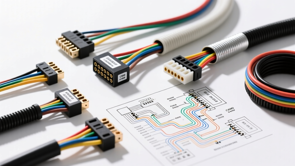
The Paradigm Shift: From Point-to-Point to Multiplexed Architectures
For decades, interpreting electrical wiring diagrams for cars meant tracing simple 12-volt point-to-point circuits: power from the battery, through a fuse, into a switch, and out to a load before returning to a chassis ground. Today, modern vehicles contain over three miles of wiring and upwards of 100 Electronic Control Units (ECUs). The modern schematic is no longer just a map of power and ground; it is a complex blueprint of multiplexed data networks, pulse-width modulated (PWM) signals, and localized interconnect networks (LIN).
As an advanced automotive technician, relying on a digital multimeter (DMM) to diagnose modern network faults is insufficient. You must learn to read OEM schematics to understand data topology, termination resistor placement, splice pack locations, and specific connector cavity matrices. This deep dive will elevate your ability to trace complex circuits, decode manufacturer-specific nomenclature, and pair schematic data with oscilloscope diagnostics.
Decoding OEM Nomenclature: Wire Specs, Colors, and DIN Standards
Before tracing a circuit, you must understand the language of the schematic. Global manufacturers utilize specific standards to denote wire size, color, and terminal designation.
Cross-Sectional Area vs. AWG and SAE J1128
While North American aftermarket diagrams often use American Wire Gauge (AWG), OEM schematics—especially from European and Asian manufacturers—use metric cross-sectional area (mm²). Understanding the conversion and the current-carrying capacity defined by standards like SAE J1128 is critical for voltage drop calculations.
- 0.35 mm² (approx. 22 AWG): Standard for High-Speed CAN (HS-CAN) and LIN bus data lines. Rated for roughly 5-7 amps, but used strictly for low-current data transmission.
- 0.50 mm² (approx. 20 AWG): Common for sensor reference voltages (5V VREF) and low-current actuator grounds.
- 0.75 mm² (approx. 18 AWG): Standard for injector control circuits and ignition coil primary triggers.
- 2.0 mm² to 5.0 mm² (14 to 10 AWG): Used for high-current module power feeds (e.g., ABS module, cooling fan relays).
Wire colors in schematics are typically abbreviated using a base color and a tracer (stripe) color. For example, WH/LG denotes a White wire with a Light Green tracer. General Motors often uses DK GRN (Dark Green) for CAN-High and DK BLU (Dark Blue) for CAN-Low, while Ford frequently utilizes WH/RD and WH/BL for their MS-CAN networks.
DIN 72552 Terminal Designations
Many global schematics still reference DIN 72552 standard terminal numbers to identify common circuit nodes, regardless of the wire color. Memorizing these saves hours of tracing:
- Terminal 15: Switched ignition power (Run/Start).
- Terminal 30: Constant battery power (Hot at all times).
- Terminal 31: Chassis ground (Battery negative).
- Terminal 50: Starter motor control (Crank signal).
- Terminal 87/30: Standard ISO relay output and input contacts.
Deep Dive: Tracing High-Speed CAN Bus Topologies in Schematics
The most critical aspect of reading modern electrical wiring diagrams for cars is understanding the Controller Area Network (CAN) bus. Unlike a simple parallel circuit, a CAN bus is a daisy-chained, twisted-pair network that requires precise electrical characteristics to function. According to the ISO 11898-2 standard, HS-CAN operates at up to 500 kbps and requires strict physical layer parameters.
| Protocol | Topology / Wire Type | Typical Wire Gauge | Voltage Levels (Recessive / Dominant) | Common OEM Wire Colors |
|---|---|---|---|---|
| HS-CAN (ISO 11898) | Linear Bus, Twisted Pair (33-50 twists/m) | 0.35 mm² (22 AWG) | CAN-H: 2.5V / 3.5V CAN-L: 2.5V / 1.5V |
GM: DK GRN / DK BLU Ford: WH/RD / WH/BL |
| MS-CAN / FT-CAN | Linear Bus, Twisted Pair | 0.35 mm² (22 AWG) | CAN-H: 2.5V / 3.0V CAN-L: 2.5V / 2.0V |
Ford: WH/LG / WH/LB |
| LIN Bus (ISO 17987) | Single Wire, Master-Slave | 0.50 mm² (20 AWG) | Recessive: 12V Dominant: 1.0V |
GM: TN (Tan) Chrysler: VT/LG |
OBD-II DLC Breakdown and the 120-Ohm Termination Rule
When a schematic shows the Data Link Connector (DLC), you must immediately look for the network termination resistors. A properly functioning HS-CAN bus requires exactly 60 ohms of resistance measured between CAN-H (DLC Pin 6) and CAN-L (DLC Pin 14) with the battery disconnected. This is achieved by placing two 120-ohm resistors in parallel at the physical ends of the network bus—usually inside the PCM and the ABS module, or a dedicated gateway module.
If your DMM reads 120 ohms, the schematic will help you identify which end of the bus has suffered an open circuit. If you read 0 ohms, the schematic will guide you to the likely short-to-ground or short-together points, often found where the harness passes through the firewall bulkhead connector.
Identifying Hidden Failure Points: Splice Packs and Ground Nodes
Advanced diagnostics require looking beyond the components and focusing on the nodes where circuits intersect. OEM schematics explicitly mark Splice Packs (e.g., S100, S203) and Ground Nodes (e.g., G100, G203). These are the most common points of failure in aging vehicles due to galvanic corrosion, thermal cycling, and vibration.
Common OEM Ground Node Failures
Ground nodes are not always simple ring terminals bolted to bare metal. Modern vehicles use centralized ground studs or splice packs encapsulated in butyl mastic to prevent moisture intrusion. When reading a diagram, note the physical location description:
- GM G100 / G203: Often located behind the left and right kick panels or A-pillars. A poor connection here will cause cascading failures across multiple seemingly unrelated modules (e.g., BCM, HVAC, and Radio) because they share the same ground return path.
- Chrysler Z1 / Z2: Frequently located in the engine bay near the strut towers or integrated into the Integrated Power Module (IPM). Corrosion here mimics failed PCM drivers.
- Ford G200 Series: Often found behind the dashboard or under the carpet near the transmission hump. Water intrusion from clogged AC evaporator drains frequently destroys these ground nodes, leading to high-resistance ground returns that back-feed 5V reference circuits.
Advanced Diagnostic Workflow: Schematic to Oscilloscope
The ultimate test of your ability to read electrical wiring diagrams for cars is pairing the schematic with a Digital Storage Oscilloscope (DSO). A DMM averages voltage over time, masking microsecond network faults. As detailed in the Pico Technology automotive testing library, visualizing the physical layer of the network confirms the schematic's topology.
Step-by-Step DSO Verification
- Identify the Access Point: Use the schematic to find a non-intrusive breakout point, such as the OBD-II DLC or a module connector with accessible back-probing pins. Never pierce the wire insulation, as this compromises the twisted-pair geometry and invites corrosion.
- Configure the DSO: Set Channel A to CAN-H and Channel B to CAN-L. Set the timebase to 20 µs/div and voltage range to ±10V to capture the dominant and recessive states.
- Verify the Differential Signal: The schematic tells you it is a differential pair. On the scope, CAN-H should mirror CAN-L perfectly. If CAN-H spikes to 3.5V, CAN-L must simultaneously drop to 1.5V. The sum of the two channels should always equal roughly 5.0V.
- Analyze the Recessive State: Look at the baseline (recessive state). Both lines should sit flat at 2.5V. If you see ringing, overshoot, or a stepped baseline, the schematic will help you trace the bus to find a missing termination resistor, a stub line that is too long (violating the ISO 11898 max stub length of 0.3 meters), or physical damage to the twisted pair.
Conclusion: The Schematic as a Diagnostic Roadmap
Mastering electrical wiring diagrams for cars is no longer about finding a broken wire; it is about understanding the architecture of the vehicle's nervous system. By combining a deep knowledge of OEM nomenclature, network topology standards, and precise oscilloscope verification, you transition from a parts-swapper to a true automotive electrical engineer. Always trust the schematic, verify the physical layer, and let the data guide your diagnostic path.