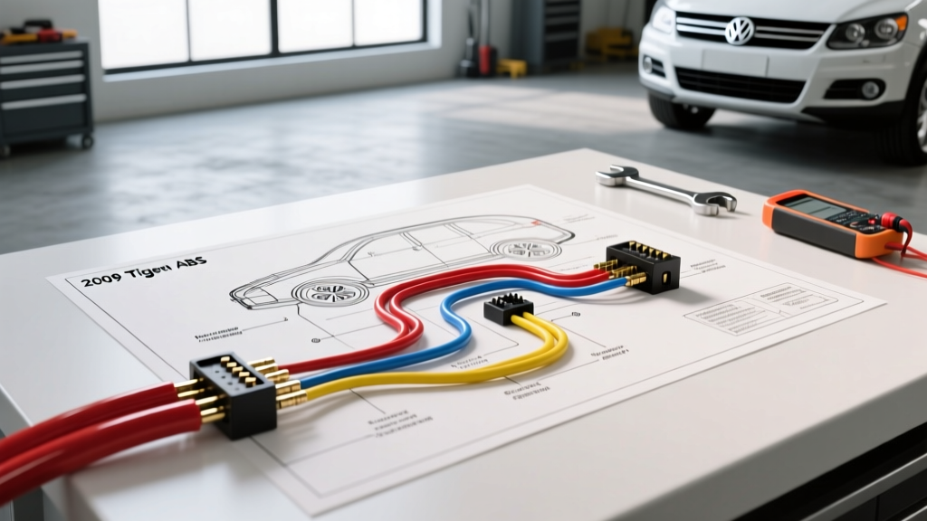
Understanding the 2009 VW Tiguan ABS/ESP Architecture
When consulting a 2009 VW Tiguan ABS wiring diagram, technicians and DIYers must recognize that this vehicle is built on Volkswagen's PQ35 platform. This architecture utilizes a highly integrated Bosch ABS/ESP control module (designated as J104) that manages not only anti-lock braking and traction control but also communicates heavily with the steering angle sensor (G85), yaw rate sensor (G202), and the engine control module (ECM). Because the ABS module acts as a gateway for critical drivetrain CAN-bus networks, a single wiring error can cascade into multiple dashboard warning lights, including the airbag system. This guide highlights the most common wiring mistakes, severe safety hazards, and exact pinout specifications required to service the Tiguan's braking electrical system safely.
Critical Safety Warnings Before Probing
1. High-Current Hydraulic Pump Motor Circuits
The ABS hydraulic pump motor (V64) draws massive transient current—often peaking above 60 amps during an ESP intervention event. The main power feed to the T47 connector is protected by a high-amperage fuse in the engine bay fuse box (typically 40A or 50A). Warning: Never attempt to bypass a blown ABS main fuse with a higher-rated fuse or a jumper wire. Doing so can melt the 6.0mm² (approx. 10 AWG) harness wiring and cause an under-hood electrical fire. Always diagnose the pump motor for internal short circuits using a clamp meter before replacing fuses.
2. CAN-Bus Network Isolation and Airbag Interaction
The J104 module interfaces with the Powertrain CAN-bus (CAN-Antrieb). If you accidentally short the CAN-High or CAN-Low lines to ground while backprobing, you will crash the entire network. On the 2009 Tiguan, a CAN-bus dropout at the ABS module will instantly disable the Electronic Stability Program (ESP), illuminate the ABS light, and frequently trigger an Airbag Control Module (J234) fault because the airbag system relies on vehicle speed and deceleration data from the ABS module to determine deployment timing. Always disconnect the negative battery terminal and wait 15 minutes for the airbag capacitors to discharge before working near the ABS harness.
Top 5 Wiring Mistakes on the Tiguan ABS Module (J104)
Mistake 1: Using Test Lights on CAN-Bus Lines
A frequent and catastrophic error is using a standard 12V incandescent test light to check for power on the ABS connector. If a technician accidentally probes Pin 13 (CAN-High) or Pin 14 (CAN-Low) with a test light connected to battery positive, the sudden current draw will instantly fry the internal CAN transceiver chip on the J104 module's circuit board. Correction: Only use a high-impedance digital multimeter (DMM) with a minimum input impedance of 10 Megohms, or a dedicated automotive oscilloscope to read the 2.5V/1.5V differential CAN signals.
Mistake 2: Treating Active Wheel Speed Sensors as Passive
Older vehicles used passive inductive wheel speed sensors that generated an AC voltage and could be tested for resistance (typically 1,000 to 2,500 ohms). The 2009 Tiguan uses active magneto-resistive (AMR) or Hall-effect sensors. These sensors require a 12V reference voltage from the ABS module and output a square-wave current signal (typically toggling between 7mA and 14mA). Applying ohmmeter test voltage to an active sensor can destroy its internal ASIC diode. Furthermore, attempting to swap the two wires at the sensor pigtail will result in a reversed signal or a hard fault, as the internal circuitry is polarity-sensitive.
Mistake 3: Ignoring Strut Tower Ground Corrosion
The ABS module relies on a dedicated chassis ground, typically located on the left strut tower (Ground Point 6). Because this area is exposed to road salt, water ingress, and extreme temperature cycling, the M6 ground bolt and ring terminals frequently suffer from galvanic corrosion. A poor ground introduces voltage drops that the J104 module interprets as erratic wheel speed sensor signals, triggering phantom ABS activations on dry pavement. Always remove, wire-brush, apply dielectric grease, and re-torque this ground to 9 Nm (80 in-lbs) during any ABS diagnostic routine.
Mistake 4: Backprobing the T47 Connector with Standard Pins
The 47-pin T47 connector uses miniature, sealed weather-pack terminals. Forcing standard paperclips or oversized T-pins into the rear of the connector to backprobe circuits will spread the female terminal tangs. This ruins the tension of the receptacle, leading to micro-arcing, localized melting, and intermittent ABS faults that only occur when hitting bumps. Use the proper VW VAS 1978 terminal extraction and backprobing kit to ensure the seal and terminal integrity remain intact.
Mistake 5: Incorrect Splicing in the Engine Bay
When repairing chewed or corroded wheel speed sensor harnesses, many technicians use cheap, non-adhesive heat shrink and standard rosin-core solder. Under-hood environments require dual-wall, adhesive-lined marine heat shrink and acid-free solder. Standard heat shrink will wick moisture via capillary action into the twisted-pair sensor wires, leading to internal green-copper corrosion that alters the signal impedance and triggers a wheel speed sensor implausibility code (e.g., P0500 series or VAG-specific 00285).
2009 VW Tiguan ABS Control Module (T47) Pinout Reference
Below is a structured reference for the most critical circuits entering the J104 ABS module via the main T47 harness connector. Always verify against the factory wiring diagram using your specific VIN, as mid-year production changes can alter wire colors.
| Pin | Wire Color | Cross-Section / AWG | Function / Destination |
|---|---|---|---|
| 13 | Orange / Black | 0.5mm² (20 AWG) | CAN-High (Powertrain CAN-Bus) |
| 14 | Orange / Brown | 0.5mm² (20 AWG) | CAN-Low (Powertrain CAN-Bus) |
| 46 | Red | 6.0mm² (10 AWG) | Terminal 30 (Battery + via Main ABS Fuse) |
| 47 | Black | 1.5mm² (15 AWG) | Terminal 15 (Ignition Switched Power) |
| 1 & 2 | Black/Red & Black/Blue | 0.35mm² (22 AWG) | Right Front Wheel Speed Sensor (Twisted Pair) |
| 3 & 4 | Black/Green & Black/Yellow | 0.35mm² (22 AWG) | Left Front Wheel Speed Sensor (Twisted Pair) |
| GND | Brown | 6.0mm² (10 AWG) | Main Chassis Ground (Left Strut Tower) |
Symptom-Cause-Fix Decision Tree for ABS Wiring Faults
- Symptom: ABS, ESP, and Airbag lights illuminate simultaneously after a cold start.
- Probable Cause: Voltage drop on Terminal 30 (Pin 46) or corroded strut tower ground.
- Fix: Perform a voltage drop test across the main power feed and ground circuit with the ignition ON. Clean ground point and apply anti-corrosion compound.
- Symptom: Intermittent "Wheel Speed Sensor Implausible Signal" code for one specific corner, occurring only over rough roads.
- Probable Cause: Spread terminal inside the T47 connector or micro-fracture in the sensor pigtail harness near the steering knuckle.
- Fix: Inspect the T47 pin with a magnifying glass for terminal spread. Perform a continuity wiggle-test on the sensor harness using a DMM. Replace the sensor harness if the wire breaks internally.
- Symptom: ABS pump runs continuously after the ignition is turned off, draining the battery.
- Probable Cause: Internal short inside the J104 control module or a stuck ABS main relay (if equipped externally).
- Fix: Pull the main ABS fuse immediately to save the battery and prevent pump burnout. The J104 module requires professional rebuilding or replacement and subsequent coding via VCDS/ODIS.
Proper Diagnostic Procedures & Tooling
To accurately diagnose the 2009 VW Tiguan ABS system, a standard OBD2 scanner is insufficient. You must use a VAG-specific diagnostic tool like VCDS (VAG-COM) or the factory ODIS (Offboard Diagnostic Information System) to access the Address 03 (ABS Brakes) module. These tools allow you to view live Measured Value Blocks (MVBs) to monitor individual wheel speed sensor outputs in real-time while driving. When measuring active wheel speed sensors, use an oscilloscope to verify the clean square-wave output and ensure the signal voltage toggles precisely between 0.8V (Low) and 1.6V (High) relative to the module's internal reference ground.
Authoritative References
- VW ErWin Official Service Manuals - Factory wiring diagrams, T47 pinout charts, and ground point locations for the PQ35 platform.
- SAE International J1939 / CAN Standards - Technical specifications for automotive high-speed CAN-bus physical layer requirements and troubleshooting.
- Bosch Automotive Electrics and Electronics - Reference documentation on active magneto-resistive wheel speed sensor operation and ABS hydraulic pump architectures.