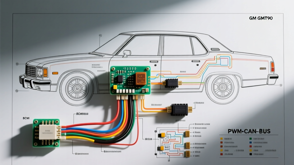
The Evolution of the Car Lighting Wiring Diagram
When interpreting a modern car lighting wiring diagram, automotive technicians must look far beyond simple switch-to-bulb continuity. The days of a 14 AWG wire running directly from a mechanical headlight switch through a firewall bulkhead connector to a sealed beam are largely over. In modern multiplexed architectures, the headlight switch is merely a low-current multiplexed input module sending a Class 2 or CAN-Bus serial data message to the Body Control Module (BCM). The BCM then processes this request, checks for vehicle state parameters (like ignition status and ambient light sensor inputs), and ultimately drives the lighting circuits using solid-state relays (SSRs) or pulse width modulation (PWM).
This advanced technical deep dive focuses on the ubiquitous GM GMT900 platform (2007-2013 Chevrolet Silverado, GMC Sierra, Tahoe, and Suburban). By dissecting this specific car lighting wiring diagram, we will explore BCM pinouts, PWM diagnostics, CAN-Bus bulb-out detection logic, and the precise methodology for integrating high-current relay harnesses without triggering BCM fault codes.
GMT900 Platform: BCM-Controlled Headlight Architecture
On the GMT900 platform, the exterior lighting is heavily managed by the BCM, located under the left side of the instrument panel. The headlamp switch assembly communicates with the BCM via a serial data bus. Once the BCM receives a valid 'Headlamps On' request, it grounds the internal control coils of the underhood fuse block (UHFB) relays or directly powers the lighting circuits depending on the specific trim and RPO codes.
For the low beam headlamps, the BCM provides the ground path for the UHFB low beam relays. The main power feed originates from the 15A 'LO BEAM' fuses. Understanding this relay-control logic is critical; if you are probing the headlamp connector at the front of the vehicle and see no voltage, the fault could lie in a failed BCM internal driver, a corroded UHFB relay coil ground, or a voltage drop on the serial data line.
Body Control Module (BCM) Pinout and Wire Specifications
The following table details the critical BCM connector pinouts for the GMT900 headlight and daytime running lamp (DRL) circuits. Note that GM utilizes specific wire insulation colors and gauge sizes to manage voltage drop across the chassis.
| Circuit Function | BCM Connector / Pin | Wire Color | AWG Size | Destination / Component |
|---|---|---|---|---|
| Left Low Beam Relay Control | X1 (Black) / Pin 42 | Dark Green (DK GRN) | 18 AWG | UHFB Lo Beam Relay Coil |
| Right Low Beam Relay Control | X1 (Black) / Pin 43 | Dark Blue (DK BLU) | 18 AWG | UHFB Lo Beam Relay Coil |
| High Beam Relay Control | X2 (Grey) / Pin 15 | Yellow (YEL) | 18 AWG | UHFB Hi Beam Relay Coil |
| Headlamp Switch Signal (MUX) | X3 (Brown) / Pin 11 | Brown/White (BRN/WHT) | 22 AWG | Headlamp Switch Assembly |
| BCM Main Ground (Lighting) | X5 (Green) / Pin 28 | Black (BLK) | 14 AWG | Ground Splice Pack G203 |
Pulse Width Modulation (PWM) and CAN-Bus Diagnostics
One of the most misunderstood aspects of modern automotive electrical systems is how the BCM monitors bulb integrity and manages Daytime Running Lamps (DRL). According to SAE International J1292 standards for automobile lighting, DRLs must meet specific candela requirements while minimizing glare and power consumption. To achieve this, the GMT900 BCM utilizes Pulse Width Modulation (PWM) on the low beam circuits when operating in DRL mode.
Instead of dropping voltage via a resistor (which generates massive heat and wastes energy), the BCM switches the ground circuit on and off at a high frequency—typically between 400 Hz and 1 kHz. By altering the duty cycle (e.g., 50% on-time, 50% off-time), the halogen filament receives an average of 6 volts, burning dimmer and lasting longer while remaining fully compliant with NHTSA FMVSS 108 regulations.
Oscilloscope Waveform Analysis for DRL and Bulb-Out Detection
If you attempt to diagnose a PWM-controlled DRL circuit with a standard digital multimeter (DMM), you will read a fluctuating, seemingly erratic DC voltage (often hovering around 6V to 8V). This is useless for advanced diagnostics. You must use a digital storage oscilloscope (DSO).
- Timebase Setup: Set to 2ms to 5ms per division to clearly capture the 400 Hz square wave.
- Voltage Scale: Set to 5V per division. You should see a clean 0V to 12V square wave.
- Duty Cycle Measurement: In DRL mode, expect a 40-60% duty cycle. When the headlight switch is turned fully ON, the BCM transitions to a 100% duty cycle (solid 12V ground).
Furthermore, the BCM uses this PWM signal for 'bulb-out' detection. By monitoring the current ramp-up (inrush current) and the steady-state current draw during the 'ON' portion of the PWM cycle, the BCM calculates the resistance of the filament. A standard H11 halogen bulb draws approximately 4.5 Amps (55 Watts). If the BCM detects a draw of less than 1 Amp, it assumes the filament is broken, sets a Diagnostic Trouble Code (DTC) such as B2520 (Headlamp Low Beam Circuit), and sends a serial data message to the Driver Information Center (DIC) to display 'Service Low Beam'.
Troubleshooting Decision Tree: Multiplexed Lighting Faults
When facing a no-light condition on a BCM-controlled circuit, follow this structured diagnostic path to isolate the fault without throwing unnecessary parts at the vehicle:
- Verify the Switch Request: Connect a scan tool and monitor the BCM data stream. Look for the 'Headlamp Switch Signal' parameter. If it does not change state when the stalk is turned, the fault is in the switch assembly or the 22 AWG MUX wiring.
- Check for Active DTCs: If the BCM sets a 'Circuit Open' or 'Circuit Short to Ground' DTC, the BCM has already disabled the internal solid-state driver to protect its circuitry. You must clear the code and repair the physical wiring before the BCM will attempt to power the circuit again.
- Perform a Voltage Drop Test on the Power Feed: With the relay commanded ON, measure voltage from the battery positive post to the power pin at the headlamp connector. A reading above 0.5V indicates high resistance in the UHFB fuse, relay contacts, or the 14 AWG chassis wiring.
- Verify the BCM Ground Path: Backprobe the BCM control wire (e.g., Pin 42 for Left Low Beam). With the lights commanded ON, you should read less than 0.2V relative to battery negative. If you read 12V, the BCM is not grounding the relay coil (internal BCM failure or open control wire).
Bypassing the BCM: High-Current Relay Integration
Upgrading to high-output LED light bars, off-road rally lamps, or high-draw HID ballasts directly on the factory wiring is a catastrophic mistake. The 18 AWG control wires and factory relays are not rated for the inrush currents of large capacitive ballasts. Furthermore, altering the current draw will immediately trigger the BCM's bulb-out detection logic.
To integrate auxiliary lighting while respecting the factory car lighting wiring diagram, you must construct a relay bypass harness. This allows the factory circuit to act solely as a low-current trigger.
Relay Harness Construction and Delphi Connector Standards
For auxiliary lighting integration, use a standard Bosch-style 5-pin relay (Terminals 30, 85, 86, 87, 87a). The construction requires strict adherence to automotive connector standards to prevent moisture ingress and voltage drop. As detailed in foundational resources like the AutoShop 101 Electrical Circuits Guide, proper crimping and sealing are non-negotiable.
- Trigger Circuit (Pins 85 & 86): Tap into the factory 18 AWG headlamp control wire using a T-tap or, preferably, by cutting the wire and using a Delphi Metri-Pack 280 series inline splice. Pin 85 connects to the factory trigger wire. Pin 86 connects to a clean, dedicated chassis ground (using a ring terminal and star washer on bare metal).
- High-Current Feed (Pin 30): Run a new 10 AWG primary wire directly from the battery positive terminal. This wire MUST be protected by an inline Maxi-fuse (rated for 125% of the auxiliary light's total amperage draw) located within 8 inches of the battery post.
- Load Output (Pin 87): Run 12 AWG wire from Pin 87 to the auxiliary lighting relay or directly to the ballasts.
- Connector Selection: For all external connections in the engine bay, use Delphi Weather-Pack or Metri-Pack 630 series connectors with silicone secondary locks and weather seals. Never use exposed butt-splices or electrical tape in the engine compartment; capillary action will wick moisture into the copper strands, leading to green corrosion and eventual open-circuit failures.
By utilizing the factory headlamp signal to trigger an external relay, you maintain the OEM functionality of the headlight switch, preserve the BCM's PWM DRL logic (the external relay will simply click rapidly during DRL mode, or you can use a PWM-filtering capacitor if the relay chatters excessively), and ensure that high amperage loads bypass the delicate traces of the factory UHFB and BCM entirely.
Authoritative References
For further study on automotive lighting standards, multiplexed electrical architectures, and connector terminal crimp specifications, refer to the following industry-standard documentation: