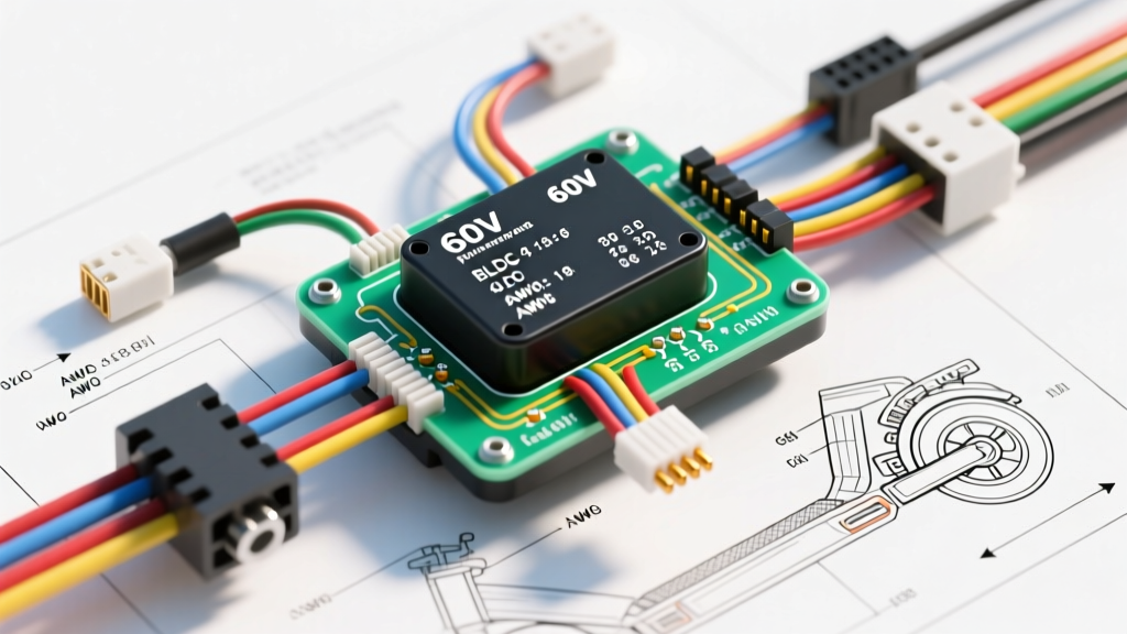
Decoding the 60V Electric Scooter Controller Wiring Diagram
When technicians, micro-mobility mechanics, and DIY builders search for a 60v electric scooter controller wiring diagram pdf, they are typically looking for a definitive reference to map out the complex network of high-current power delivery and low-voltage signal logic. Modern 60V brushless DC (BLDC) motor controllers act as the central nervous system of high-performance electric scooters, managing everything from sinusoidal phase commutation to regenerative braking. While OEM PDF schematics provide the foundational block diagrams, translating those 2D schematics into physical, reliable wiring harnesses requires a deep understanding of AWG ratings, connector metallurgy, and signal tolerances.
This technical specification reference serves as the textual equivalent of a comprehensive 60V controller wiring diagram. We break down the exact pinouts, wire color codes, and diagnostic procedures required to safely wire, test, and troubleshoot a 60V nominal (67.2V fully charged 16S Li-ion) electric scooter powertrain.
High-Current Power and Phase Circuit Specifications
The high-current side of the controller is responsible for transferring raw DC battery power and converting it into a 3-phase AC square or sine wave. Improper gauge sizing or poor termination here leads to voltage sag, connector melting, and catastrophic MOSFET failure.
Battery and Main Power Inputs
For a standard 60V 35A continuous (50A peak) controller, the main battery leads must handle significant thermal loads. According to SAE J1128 standards for low-tension primary cables, wire gauge must be selected based on both current capacity and the high-temperature environment of an enclosed scooter deck.
- Wire Gauge: 10 AWG high-strand-count silicone wire (minimum 105°C rating).
- Color Code: Red (Battery B+ / VCC), Black (Battery B- / GND).
- Connector: XT90-S Anti-Spark. The anti-spark resistor is critical in 60V systems to prevent inrush current from damaging the controller's primary filter capacitors upon connection.
- Ignition/Accessory Wire: 18 AWG Red. This low-current wire is tied to the B+ line via a keyed ignition switch to wake the controller's logic board without routing high current through the handlebars.
Motor Phase Outputs (U, V, W)
The phase wires carry the high-amperage alternating current that physically drives the BLDC hub motor. The physical sequence of these wires dictates motor rotation direction.
- Wire Gauge: 12 AWG or 10 AWG silicone wire (12 AWG is acceptable for runs under 12 inches; use 10 AWG for longer routing through swingarms).
- Color Code: Yellow (Phase U), Green (Phase V), Blue (Phase W).
- Connector: 5mm or 6mm Gold-Plated Bullet Connectors. Always use adhesive-lined marine heat shrink to prevent moisture ingress and phase-to-phase shorting, which will instantly destroy the controller's MOSFET bridge.
Low-Current Signal and Sensor Pinouts
The low-current harness relies on precise 5V logic signals. Miswiring these connectors is the leading cause of 'no-start' conditions and erratic throttle behavior. Most modern 60V controllers utilize JST-SM or XH2.54 pitch connectors for these circuits.
Hall Effect Sensor Connector (5-Pin)
The Hall sensors inside the motor provide real-time rotor position data to the controller, allowing for precise electronic commutation. The standard 5-pin JST-SM layout is as follows:
- Pin 1 (Red): +5V VCC (Logic Power)
- Pin 2 (Black): Ground (GND)
- Pin 3 (Yellow): Hall Signal A
- Pin 4 (Green): Hall Signal B
- Pin 5 (Blue): Hall Signal C
Expert Note: If the motor stutters or 'cogs' under load, the Hall sensor phase angle (60° vs 120°) or the sequence (A-B-C) is mismatched with the controller's internal firmware map. Refer to Texas Instruments BLDC commutation application notes for the mathematical relationship between Hall states and phase energization.
Throttle and Brake Cut-off Switches
The throttle circuit uses a linear Hall-effect sensor to translate mechanical twist into a voltage gradient.
- Throttle Pinout (3-Pin): Red (+5V), White or Green (Signal), Black (GND).
- Signal Voltage Curve: A healthy throttle outputs 0.8V - 1.1V at rest, scaling linearly to 4.2V - 4.5V at full twist. If the controller reads above 4.8V or below 0.5V, it will trigger a high/low voltage protection fault (Error Code 04 or 08 on most LCD displays).
- Brake Cut-off (2-Pin): Normally Open (NO) or Normally Closed (NC) mechanical switch. Pulling the brake lever breaks the 5V signal or grounds the E-ABS pin, instantly cutting phase power and optionally engaging electronic braking.
Comprehensive 60V Controller Wiring Specification Table
| Circuit Function | Wire Color(s) | AWG Size | Connector Type | Voltage / Signal Type |
|---|---|---|---|---|
| Main Battery B+ | Red | 10 AWG | XT90 Anti-Spark | 60V Nom / 67.2V Max DC |
| Main Battery B- | Black | 10 AWG | XT90 Anti-Spark | Ground Reference |
| Motor Phase U | Yellow | 12 AWG | 5mm Gold Bullet | 3-Phase AC (PWM) |
| Motor Phase V | Green | 12 AWG | 5mm Gold Bullet | 3-Phase AC (PWM) |
| Motor Phase W | Blue | 12 AWG | 5mm Gold Bullet | 3-Phase AC (PWM) |
| Hall Sensor Power | Red / Black | 22 AWG | JST-SM 5-Pin | 5V DC / GND |
| Hall Signals A, B, C | Yel, Grn, Blu | 22 AWG | JST-SM 5-Pin | 5V Digital Square Wave |
| Throttle Signal | White / Green | 22 AWG | JST-SM 3-Pin | 0.8V to 4.5V Analog |
| Ignition / Lock | Red (Thin) | 18 AWG | Spade / JST | 67.2V DC (Switched) |
Accessing and Interpreting OEM PDF Schematics
When you finally locate the correct OEM 60v electric scooter controller wiring diagram pdf for your specific make (such as Dualtron, Kaabo, or Apollo), you will notice that manufacturers rarely use standard AWG color codes in their block diagrams. Instead, they use proprietary pin numbers and harness wrap colors. To bridge the gap between the PDF schematic and physical repair:
- Identify the Controller IC: Look for the main microcontroller chip on the PDF block diagram (often an STM8 or STM32 series). This confirms the logic voltage (usually 3.3V stepped up to 5V for external peripherals).
- Trace the Shunt Resistor: The PDF will show a thick trace leading to a shunt resistor. This is how the controller measures amperage. If your scooter is throwing overcurrent faults, the solder joints on this physical shunt are likely cracked.
- Cross-Reference Pinouts: Use resources like Electric Scooter Parts wiring archives to cross-reference generic 60V pinouts if your specific OEM PDF uses ambiguous translated terminology (e.g., 'Electric Door' instead of 'Phase U').
Diagnostic Troubleshooting for 60V BLDC Systems
Use this symptom-cause-fix decision tree when a newly wired 60V system fails to operate correctly.
Symptom: Motor Stutters, Vibrates, or 'Coggs' Under Load
- Cause 1: Phase wire sequence mismatch. Fix: Swap any two phase wires (e.g., Yellow and Green) and swap the corresponding Hall sensor wires to maintain the 120-degree timing offset.
- Cause 2: Blown Hall sensor inside the motor stator. Fix: Use a multimeter to back-probe the 5-pin connector. With the ignition on, rotate the wheel by hand. The signal pins should pulse between 0V and 5V. A pin stuck at 0V or 5V indicates a burned Hall IC.
Symptom: Controller Overheating and Thermal Shutdown
- Cause 1: Undersized phase wires or poor bullet connector crimps causing high resistance. Fix: Inspect bullet connectors for blackened plastic. Cut, strip, and re-solder using rosin-core flux and adhesive heat shrink.
- Cause 2: Incorrect Hall sensor angle (60° vs 120°). If a 120° motor is driven with a 60° commutation map, the controller will pump massive reactive current into the stator without generating proportional torque, leading to rapid MOSFET overheating. Fix: Reprogram the controller via the UART/RS485 diagnostic cable to match the motor's physical Hall spacing.
Symptom: Complete Loss of Power with LCD Display On
- Cause: BMS (Battery Management System) cutoff due to voltage sag, or a blown main MOSFET bank. Fix: Measure the DC voltage at the XT90 connector under load. If it drops below 48V instantly upon throttle application, the BMS is tripping. If battery voltage remains stable at the connector but the motor receives no phase voltage, the controller's internal phase bridge has shorted and requires replacement.
By treating the 60v electric scooter controller wiring diagram pdf not just as a picture, but as a roadmap of electrical tolerances and signal logic, you can ensure your high-voltage micro-mobility builds are safe, efficient, and reliable for the long haul.