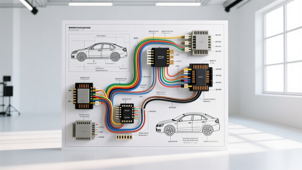
Decoding the Standard Car Audio Wiring Diagram
When interpreting a car audio wiring diagram, automotive technicians and mobile electronics installers must differentiate between legacy analog circuits and modern multiplexed data networks. Whether you are integrating an aftermarket double-DIN receiver via an ISO 10487 harness or bypassing a factory amplifier on a CAN-bus network, understanding the exact pinout, wire gauge (AWG), and color code standards is critical. A misinterpreted wiring schematic can lead to catastrophic failures, including Body Control Module (BCM) backfeeding, parasitic battery drains, or melted head unit PCBs.
This complete walkthrough dissects the universal EIA/CEA color codes, the ISO 10487 power and speaker block standards, high-current amplifier distribution, and modern data-bus integration protocols. For comprehensive vehicle-specific harness adapters, the Crutchfield Car Wiring Harness Guide remains an industry-standard reference for OEM-to-aftermarket translations.
ISO 10487 Head Unit Harness: Block A (Power & Data)
The ISO 10487 standard defines the 16-pin connector split into two 8-pin blocks. Block A handles power, ground, and auxiliary control signals. The most common installation error occurs when swapping the Constant 12V and Accessory 12V circuits, which wipes the radio's memory upon ignition-off or causes severe parasitic draws.
| ISO Pin | Function | Standard Wire Color | Recommended AWG | Technical Notes |
|---|---|---|---|---|
| Pin 1 | Speed Pulse / VSS | Green/White | 20-22 AWG | Used for GPS dead-reckoning and speed-dependent volume. |
| Pin 2 | Mute / Telephone | Brown | 20-22 AWG | Ground-to-mute circuit for Bluetooth or telematics integration. |
| Pin 3 | Dimmer / Illumination | Orange / Orange-White | 20-22 AWG | Variable voltage (0-12V) or PWM signal for dashboard dimming. |
| Pin 4 | 12V+ Constant (Memory) | Yellow | 16-18 AWG | Direct to battery via fuse. Maintains clock, presets, and DSP profiles. |
| Pin 5 | Power Antenna / Amp Turn-On | Blue / Blue-White | 18 AWG | Outputs +12V only when the radio is ON. Max draw typically 300mA. |
| Pin 6 | Illumination (Switched) | Orange-Black | 20-22 AWG | Alternative dimmer trigger depending on OEM manufacturer. |
| Pin 7 | 12V+ Accessory (Switched) | Red | 16-18 AWG | Triggered by the ignition cylinder or CAN-bus wake signal. |
| Pin 8 | Chassis Ground | Black | 14-16 AWG | Must be secured to bare, unpainted chassis metal. Never use a seatbelt bolt. |
EIA/CEA-736 Speaker Wire Color Matrix (Block B)
Block B of the ISO harness, or the proprietary 20-pin OEM connectors found in modern Ford, GM, and Toyota vehicles, adheres to the Consumer Electronics Association (CEA-736) standard for speaker polarity and phase. Proper phase alignment is mandatory; an out-of-phase speaker will result in destructive acoustic interference, completely nullifying low-frequency bass response in the cabin.
| Channel | Positive (+) Wire | Negative (-) Wire | Impedance Nominal |
|---|---|---|---|
| Left Front (LF) | White | White w/ Black Stripe | 4 Ohms |
| Right Front (RF) | Gray | Gray w/ Black Stripe | 4 Ohms |
| Left Rear (LR) | Green | Green w/ Black Stripe | 4 Ohms |
| Right Rear (RR) | Purple | Purple w/ Black Stripe | 4 Ohms |
Expert Note: When interfacing with factory amplified systems (e.g., Bose, Harman Kardon, JBL), the speaker-level outputs are often crossed over and EQ'd by the factory DSP. You must use a Digital Signal Processor (DSP) with a summing and de-EQ algorithm to flatten the signal before sending it to your aftermarket RCA pre-outs.
High-Current Amplifier Wiring: AWG & Fuse Sizing
Standard head unit wiring diagrams only cover low-current signal and power distribution. When adding external amplifiers, the Mobile Electronics Certification Program (MECP) mandates strict adherence to AWG sizing based on total RMS wattage and cable run length. Using Copper-Clad Aluminum (CCA) wire instead of Oxygen-Free Copper (OFC) requires upsizing the gauge by at least one step to compensate for higher resistance and voltage drop.
Amplifier Power Wire Specification Chart
| Total System RMS Wattage | OFC Wire Gauge (0-16 ft run) | OFC Wire Gauge (16-22 ft run) | Main Fuse Rating (ANL/MIDI) |
|---|---|---|---|
| 0 - 400W | 8 AWG | 4 AWG | 40A - 60A |
| 400W - 1000W | 4 AWG | 2 AWG | 80A - 120A |
| 1000W - 1500W | 2 AWG | 1/0 AWG | 150A - 200A |
| 1500W - 3000W+ | 1/0 AWG | 2/0 AWG | 250A - 350A |
Critical Safety Rule: The main power fuse must be installed within 18 inches of the vehicle's positive battery terminal. This protects the primary power cable from shorting to the chassis and causing an electrical fire in the event of a collision or insulation failure.
Modern Data-Bus Integration: CAN-Bus, A2B, and MOST
In vehicles manufactured after 2012, the traditional 'car audio wiring diagram' has evolved. Factory head units no longer output analog speaker signals or simple 12V turn-on wires. Instead, they communicate via CAN-bus (Controller Area Network) to request audio routing, and transmit digital audio via A2B (Automotive Audio Bus) or MOST (Media Oriented Systems Transport) fiber optic networks.
If you attempt to tap into the speaker wires of a modern FCA Uconnect or GM IntelliLink system without a CAN-bus decoding interface (like a Maestro RR or PAC RP4), the BCM will detect an impedance anomaly on the audio circuit. This triggers a 'Speaker Short' diagnostic trouble code (DTC) and shuts down the audio output entirely. Always use a data-bus interface that translates the CAN-bus wake signals and digital audio streams into standard analog RCA outputs and a 12V remote turn-on wire.
Troubleshooting Common Audio Wiring Failure Modes
Even with a perfect wiring diagram, real-world installation variables introduce complex electrical faults. Below is a diagnostic decision tree for the most common integration failures.
1. Alternator Whine (Ground Loops)
- Symptom: A high-pitched whining noise that increases in pitch with engine RPM.
- Cause: A ground loop occurs when the head unit and the amplifier are grounded at different chassis points with varying resistance, causing the RCA shield to carry the differential voltage.
- Fix: Ensure all audio components share a common, dedicated ground point. Verify that RCA cables are routed down the opposite side of the vehicle from the high-current power wires to prevent electromagnetic induction. For deep-dive EMC standards, reference SAE J1113 Electromagnetic Compatibility guidelines.
2. Parasitic Battery Draw
- Symptom: Vehicle battery dies after sitting for 24-48 hours.
- Cause: The amplifier's remote turn-on wire is tied to Pin 4 (Constant 12V) instead of Pin 7 (Accessory 12V), or a CAN-bus interface is failing to enter 'sleep' mode when the vehicle bus goes dormant.
- Fix: Use a multimeter to measure the remote wire voltage with the key off. It should drop to 0V. If using a CAN-bus adapter, ensure the firmware is updated to recognize the specific vehicle's CAN-bus sleep timers.
- Symptom: Distortion at high volumes, followed by the amp entering protect mode.
- Cause: Voltage drop at the amplifier's B+ terminal due to undersized power wire or poor ground. When voltage drops below 11.5V under load, the amp draws excessive amperage to compensate for the wattage demand (Watts = Volts x Amps), triggering thermal protection.
- Fix: Measure voltage directly at the amplifier's B+ and Ground terminals while playing a 40Hz test tone at 75% volume. If voltage drops below 12V, upgrade the power and ground wiring, or add a secondary alternator and lithium battery bank.
3. Amplifier Clipping and Thermal Shutdown
Final Integration Checklist
Before reconnecting the negative battery terminal, verify all bare wire connections are sealed with marine-grade heat shrink adhesive. T-taps and scotch-locks are strictly prohibited in professional automotive audio wiring, as they introduce micro-vibrations that sever copper strands over time, leading to intermittent shorts and high-resistance connections. By adhering strictly to the OEM pinouts and AWG specifications outlined in this walkthrough, you ensure a reliable, high-fidelity audio system that integrates seamlessly with the vehicle's complex electrical architecture.