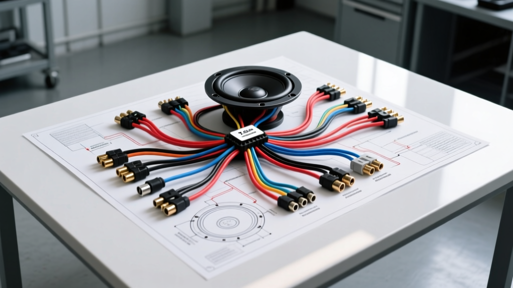
Understanding the 2 Ohm Wiring Diagram for Subwoofers
Integrating a high-output aftermarket audio system into a vehicle's electrical architecture requires precise planning. When utilizing a 2 ohm wiring diagram for subwoofers, you are intentionally dropping the impedance load to force a Class D monoblock amplifier to produce maximum wattage. While this yields significant acoustic output, it places immense thermal and electrical stress on the vehicle's charging system, the amplifier's output stage, and the speaker wire gauge. A 2-ohm load draws substantially more current than a 4-ohm load, meaning that marginal wiring or poor chassis grounds will immediately trigger amplifier protection circuits or cause severe voltage drop.
This guide provides a comprehensive, step-by-step troubleshooting flow designed for automotive electrical technicians and advanced DIY installers. We will diagnose the most common failure modes associated with 2-ohm subwoofer configurations, from parasitic voltage drops to voice coil impedance mismatches, using industry-standard diagnostic procedures.
The Core 2 Ohm Wiring Architecture
Before initiating the troubleshooting flow, verify that your baseline installation adheres to strict automotive electrical standards. According to SAE International (SAE J1128) guidelines for low-tension primary cables, wire gauge and insulation must be rated for the specific current draw and under-hood temperatures.
- Power Wire (B+): For a 1000W RMS amplifier pushing a 2-ohm load, you must use 0 AWG or 4 AWG OFC (Oxygen-Free Copper) wire. Avoid CCA (Copper-Clad Aluminum) as it suffers from higher resistance and voltage drop over distance. The main ANL fuse must be located within 18 inches of the vehicle's positive battery terminal.
- Ground Wire (B-): Must be the same AWG as the power wire. The grounding point must be sanded to bare, unpainted steel. Use a stainless steel star washer to bite into the metal, secure with a factory-grade bolt, and coat the terminal in dielectric grease to prevent galvanic corrosion.
- Remote Turn-On: 18 AWG primary wire routed from the head unit's remote output. If the head unit's remote lead sags below 10V under load, use a 12V automotive relay triggered by the head unit to switch a dedicated 12V B+ line to the amplifier's REM terminal.
- Speaker Wire: Minimum 12 AWG OFC speaker wire from the amplifier to the subwoofer enclosure. At 2 ohms, current flow is high; undersized speaker wire will act as a resistor, dissipating wattage as heat before it reaches the voice coil.
Step-by-Step Troubleshooting Decision Tree
Use the following diagnostic flow to isolate faults in your 2-ohm subwoofer system. You will need a Digital Multimeter (DMM) and a tone generator for comprehensive testing.
Symptom 1: Amplifier Enters Protect Mode Immediately Upon Power-Up
Step 1: Verify Input Voltage
Set your DMM to DC Voltage (20V range). With the vehicle running and the amplifier turned on, probe the B+ and B- terminals directly on the amplifier block (not the battery). A healthy system should read between 13.8V and 14.4V. If the reading is below 11.5V, the amplifier's undervoltage protection will engage. Proceed to Symptom 2.
Step 2: Isolate the Speaker Load
Power down the system and disconnect all speaker wires from the amplifier's output terminals. Power the system back on. If the amplifier powers up and the power LED remains green (or normal), the fault lies in the speaker wiring or the subwoofer voice coils. If the amp still goes into protect mode with no load attached, the amplifier's internal power supply or output MOSFETs are shorted.
Step 3: Test Voice Coil Impedance
With the speaker wires disconnected from the amp, set your DMM to the 200 Ohm resistance setting. Probe the positive and negative speaker wires at the amplifier end. A true 2-ohm load will typically read between 1.8 and 2.1 ohms on a DMM (accounting for wire resistance). If the DMM reads 0.0 ohms or OL (Open Loop), you have a shorted voice coil or a broken lead wire inside the subwoofer enclosure.
Symptom 2: Severe Headlight Dimming and Voltage Drop
If your headlights dim heavily on bass transients and the amplifier frequently resets, your vehicle's electrical system cannot sustain the current demands of a 2-ohm load.
Step 1: Perform the Big 3 Upgrade
The factory wiring in most passenger vehicles is not designed for 100+ amp continuous audio draws. You must upgrade three critical ground and power paths using 0 AWG OFC wire:
- Alternator positive output to the battery positive terminal.
- Engine block to the vehicle chassis.
- Battery negative terminal to the vehicle chassis.
Step 2: Check Alternator Output
According to resources from Basic Car Audio Electronics (BCAE), a standard factory alternator outputs between 70 and 110 amps. A 1000W Class D amp at 2 ohms (assuming 80% efficiency) will draw roughly 105 amps at peak output. If your alternator cannot supply this, you must upgrade to a high-output alternator (e.g., 200A+ from manufacturers like Mechman or Power Bastards).
Symptom 3: Audible Clipping and Thermal Shutdown
Step 1: Verify RCA Signal Integrity
Ensure RCA signal cables are routed strictly on the opposite side of the vehicle from the B+ power wire to prevent electromagnetic interference (EMI) and alternator whine. Check that the head unit's pre-out voltage is not exceeding the amplifier's input sensitivity, which causes front-end clipping.
Step 2: Check Voice Coil Wiring Configuration
A common error in 2-ohm diagrams is miswiring Dual Voice Coil (DVC) subwoofers, inadvertently creating a 0.5-ohm or 8-ohm load. Use the impedance matrix below to verify your physical wiring matches the target 2-ohm load.
Voice Coil Impedance Configuration Matrix
| Subwoofer Type | Wiring Method | Final Impedance | Diagram Notes |
|---|---|---|---|
| Dual 4-Ohm (DVC 4Ω) | Parallel | 2 Ohms | Connect Pos to Pos, Neg to Neg. Jumpers link the coils together. |
| Single 2-Ohm (SVC 2Ω) | Direct | 2 Ohms | Single positive and negative terminal wired directly to the amp. |
| Two SVC 4-Ohm Subs | Parallel | 2 Ohms | Wired together at the amplifier terminals or via a distribution block. |
| Dual 2-Ohm (DVC 2Ω) | Series | 4 Ohms (Warning) | Do NOT wire in parallel, as this creates a dangerous 0.5-ohm load. |
AWG and Current Draw Specifications for 2-Ohm Loads
Reference this chart to ensure your power and ground wiring can handle the amperage required by a 2-ohm load. Data based on 12V-14.4V systems with a maximum 15-foot run from the battery to the amplifier.
| Amp RMS Wattage (at 2Ω) | Estimated Max Current Draw | Minimum Wire Gauge (OFC) | Recommended Fuse Size |
|---|---|---|---|
| 500W RMS | ~55 Amps | 4 AWG | 60A ANL |
| 1000W RMS | ~105 Amps | 0 AWG | 120A ANL |
| 1500W RMS | ~155 Amps | 00 AWG (2/0) | 175A Class T |
| 2000W+ RMS | 200+ Amps | 00 AWG (2/0) or Busbar | 225A Class T |
Advanced Diagnostic Tips from the Experts
When troubleshooting a 2-ohm wiring diagram, always measure resistance at the amplifier terminals, not just at the subwoofer basket. Speaker wire adds resistance. For example, 15 feet of 12 AWG speaker wire adds approximately 0.024 ohms of resistance. While this seems negligible, in a high-current 2-ohm circuit, every fraction of an ohm affects the damping factor and the amplifier's ability to control the subwoofer's motor structure.
Furthermore, ensure your amplifier is explicitly rated for 2-ohm stability. Many older Class AB amplifiers or poorly designed Class D boards will overheat and trigger thermal protection circuits when pushed below 4 ohms. Always consult your amplifier's owner's manual and verify its CEA-2006 compliant specifications. For comprehensive wiring schematics and vehicle-specific integration guides, the Crutchfield Car Audio Learning Center remains an invaluable resource for verifying OEM head unit pre-out voltages and remote turn-on wire color codes.
Summary
A 2-ohm subwoofer configuration is the most efficient way to extract maximum power from a modern Class D monoblock amplifier. However, it leaves zero margin for error in your vehicle's electrical infrastructure. By following this step-by-step troubleshooting flow—verifying voltage at the amp, testing voice coil impedance with a DMM, and executing a Big 3 upgrade—you can eliminate protect mode faults and achieve clean, reliable bass response.