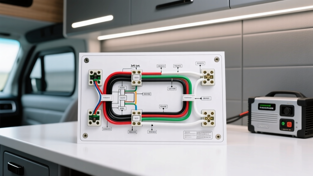
The Challenge of High-Wattage Cabin Heating in EV Conversions
When executing a luxury RV build or an electric vehicle (EV) camper conversion, cabin heating presents a massive electrical hurdle. Standard 12V DC PTC heaters draw excessive amperage (often exceeding 100A) to produce adequate BTUs, which rapidly depletes house battery banks and requires massive, expensive cabling. To solve this, advanced builders are integrating high-output pure sine wave inverters to run residential-style 240V AC heating elements. However, when builders search for a standard double pole 240 volt baseboard heater wiring diagram, they are typically looking at residential NEC codes that do not account for the vibration, mobile environments, and DC-to-AC inverter architectures of a vehicle.
This guide bridges the gap between residential HVAC schematics and automotive electrical standards. We will detail how to safely adapt a 240V baseboard heater circuit for a mobile environment, utilizing a double-pole AC contactor controlled by a 12V DC BMS (Battery Management System) interlock, ensuring compliance with SAE and NFPA mobile electrical standards.
Translating the Residential Diagram to an Automotive Inverter System
In a traditional home, a double pole 240 volt baseboard heater wiring diagram relies on a split-phase 240V residential panel, utilizing a line-voltage double-pole thermostat to break both L1 and L2 simultaneously. In an EV camper or off-grid motorhome, running 240V AC line-voltage thermostats is a severe safety hazard due to vibration-induced wire fatigue, lack of IP-rated enclosures, and the risk of lethal AC shock in a grounded metal chassis.
Core System Architecture
Instead of a line-voltage thermostat, the automotive adaptation uses a 12V DC low-voltage control circuit. The 240V AC output from the inverter feeds directly into a heavy-duty double-pole AC contactor. The contactor's coil is triggered by a 12V DC smart thermostat or a manual dash-mounted toggle switch, which is interlocked with the vehicle's BMS to prevent deep-discharge of the high-voltage traction battery or the 12V house bank.
Double-Pole Contactor Pinout and 12V DC Control Integration
To safely switch the 240V AC load, we utilize an automotive/marine-rated double-pole contactor (e.g., Schneider Electric LC1D series or an Albright SW180 equivalent adapted for AC). Below is the critical pin configuration for bridging the 240V AC power circuit with the 12V DC control circuit.
| Terminal / Pin | Function | Wire Color (Mobile Standard) | AWG Size | Torque Spec |
|---|---|---|---|---|
| L1 (Line In 1) | 240V AC Phase 1 from Inverter | Black (THHN/MTW) | 10 AWG | 1.2 Nm |
| L2 (Line In 2) | 240V AC Phase 2 from Inverter | Red (THHN/MTW) | 10 AWG | 1.2 Nm |
| T1 (Load Out 1) | 240V AC Phase 1 to Heater Element | Black (THHN/MTW) | 12 AWG | 1.0 Nm |
| T2 (Load Out 2) | 240V AC Phase 2 to Heater Element | Red (THHN/MTW) | 12 AWG | 1.0 Nm |
| PE (Ground) | Chassis / Inverter Ground Bus | Green/Yellow Stripe | 10 AWG | 1.2 Nm |
| A1 (Coil +) | 12V DC Positive from Thermostat/BMS | Red (Primary Wire) | 16 AWG | 0.5 Nm |
| A2 (Coil -) | 12V DC Negative / Chassis Ground | Black (Primary Wire) | 16 AWG | 0.5 Nm |
Note: Always install a flyback diode (e.g., 1N4007) across the A1 and A2 coil terminals to suppress inductive voltage spikes that could damage sensitive 12V DC BMS controllers or smart thermostats when the contactor disengages.
Wire Sizing, Color Codes, and Routing Standards
Unlike residential NM-B (Romex) cable, which is prohibited in mobile applications per NFPA 70 (NEC Article 551), vehicle wiring must utilize stranded, high-flexibility wire with high-temperature insulation such as MTW, THHN, or SAE J1128 GXL/TXL. The following chart dictates the minimum AWG requirements based on the heater's wattage and the continuous draw on the 240V AC inverter.
| Heater Wattage | AC Amperage (240V) | Min Inverter Size (Continuous) | AC Wire Size (L1/L2) | DC Inverter Input Cable (48V System) |
|---|---|---|---|---|
| 1000W | 4.16A | 1500W | 14 AWG | 2/0 AWG |
| 1500W | 6.25A | 2000W | 12 AWG | 2/0 AWG |
| 2000W | 8.33A | 3000W | 10 AWG | 4/0 AWG |
| 2500W | 10.41A | 3000W+ | 10 AWG | 4/0 AWG |
Routing the 240V AC lines requires strict separation from 12V DC control wires to prevent electromagnetic interference (EMI) and induction heating. Maintain a minimum 2-inch separation between the 240V AC Black/Red conductors and any 12V DC communication or sensor wiring. All AC wiring must be housed in split-loom corrugated tubing and secured with vibration-resistant adhesive-backed clamps every 8 inches.
BMS Interlocks and Overcurrent Protection
Running a 2000W resistive load on a mobile inverter system will pull approximately 55A to 65A from a 48V DC battery bank (accounting for 90% inverter efficiency). If the battery bank drops below the low-voltage disconnect (LVD) threshold, the BMS must cut power to the heater to prevent catastrophic cell damage. According to SAE J1171 marine and RV electrical standards, overcurrent protection must be installed within 7 inches of the power source.
- DC Side Protection: Install a Class T fuse (e.g., 150A for a 3000W inverter) on the positive 48V DC cable immediately adjacent to the battery busbar. Class T fuses offer the high interrupt capacity (AIC) required for lithium iron phosphate (LiFePO4) battery banks.
- AC Side Protection: Install a 2-Pole 15A or 20A DIN-rail mounted AC circuit breaker on the AC distribution block between the inverter and the contactor L1/L2 terminals. This provides localized short-circuit and overload protection for the baseboard heater element.
- BMS Relay Integration: Wire the 12V DC negative return of the contactor coil (A2) through a BMS-controlled low-side relay. If the BMS detects a low-cell voltage (e.g., 2.8V per cell), it opens the relay, instantly dropping the contactor coil and severing the 240V AC circuit.
Troubleshooting Decision Tree: Inverter-to-Heater Faults
When the baseboard heater fails to engage in an EV camper build, the issue usually stems from inverter protection modes or contactor coil failures. Use this diagnostic tree to isolate the fault:
Symptom: Inverter Shuts Down Immediately Upon Heater Engagement
- Cause 1: Inverter overload or surge limit exceeded. (Fix: Verify the baseboard heater element resistance with a multimeter. A shorted element will draw infinite current. Replace element if resistance is near 0 ohms. Expected resistance for 1500W at 240V is ~38 ohms).
- Cause 2: DC voltage sag triggering the inverter's Low Voltage Alarm. (Fix: Measure DC voltage at the inverter terminals under load. If it drops below 42V on a 48V system, upgrade the DC interconnect cables or check for corroded busbar lugs).
Symptom: Contactor Chatters or Humms Loudly
- Cause 1: Insufficient 12V DC voltage reaching the A1/A2 coil due to voltage drop over long, undersized control wires. (Fix: Upgrade 12V control wiring from 18 AWG to 14 AWG and clean all ground terminals).
- Cause 2: Debris or oxidation on the contactor's internal AC poles causing arcing. (Fix: Replace the contactor. Do not attempt to sand or clean internal AC contacts, as this destroys the silver-alloy plating and creates a fire hazard).
Symptom: Heater Works but Trips the AC Breaker Randomly
- Cause 1: Thermal expansion of the heating element causing micro-shorts against the metal casing. (Fix: Perform a megohmmeter (Megger) test between the heater terminals and the chassis ground. Any reading below 1 Megohm indicates a failing element that must be replaced).
- Cause 2: Inverter output waveform distortion. (Fix: Ensure you are using a Pure Sine Wave inverter, such as the Victron MultiPlus-II. Modified sine wave inverters will cause severe harmonic distortion, overheating the AC breaker and the resistive heater element).
By treating the 240V AC circuit with the same rigorous vibration, fusing, and BMS-integration standards as the vehicle's high-voltage DC traction system, builders can safely harness residential baseboard heaters for silent, high-BTU off-grid cabin heating.