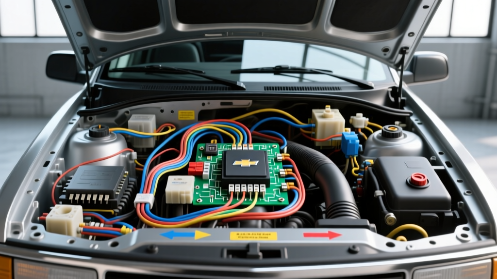
The 1998 GMT400 "Silverado" Reality: A Wiring Warning
Before diving into the schematics, we must address a critical nomenclature issue that leads many DIYers and novice technicians down the wrong diagnostic path. The 1998 Chevrolet C/K 1500/2500 (GMT400 platform) is frequently searched as the "98 Chevy Silverado." However, the Silverado nameplate officially became the primary model designation in 1999 with the GMT800 platform. In 1998, "Silverado" was merely a trim package on the C/K series. When sourcing a 98 Chevy Silverado wiring diagram, you are actually looking for the 1998 C/K 1500 Vortec schematics. Confusing the 1998 GMT400 harness with the 1999+ GMT800 harness will result in immediate misdiagnosis, as GM completely overhauled the Vehicle Control Module (VCM) architecture, data bus protocols, and sensor pinouts between these two model years.
This guide focuses strictly on the 1998 C/K series equipped with the 5.7L Vortec (L31) engine. The 1998 model year represents a mature OBD-II system utilizing GM's Class 2 Serial Data protocol. Working on this specific electrical architecture requires strict adherence to safety protocols. A single probing mistake can permanently destroy the VCM's internal serial data driver or 5-volt reference regulator. Below are the most common, catastrophic wiring mistakes made on the 1998 GMT400 platform and how to safely avoid them.
Fatal Mistake #1: Using Test Lights on 5V Reference and Class 2 Data
The most common and destructive mistake made when interpreting a 98 Chevy Silverado wiring diagram is the use of an incandescent test light or a low-impedance solenoid tester on sensitive VCM circuits. The 1998 VCM utilizes a 5-Volt Reference (5V REF) circuit to power the Throttle Position Sensor (TPS), Manifold Absolute Pressure (MAP) sensor, and other critical engine management sensors.
The 5V Reference Overload
The 5V REF wire (typically Light Blue or Dark Blue, 20 AWG) is not a standard power feed; it is a highly regulated, low-amperage voltage supply generated by an internal VCM voltage regulator. This circuit is generally designed to supply a maximum of 100 to 150 milliamps (mA) across all connected sensors. An incandescent test light draws between 250mA and 400mA to illuminate the bulb. If you pierce the 5V REF wire or back-probe the TPS connector with a test light, you will instantly overload the VCM's internal regulator. This results in a dead 5V bus, causing the engine to stall, throwing codes like P0122 (TPS Circuit Low) and P0107 (MAP Circuit Low), and permanently bricking the VCM.
The Class 2 Serial Data Trap
The 1998 GMT400 uses the Class 2 Serial Data bus for module-to-module communication (VCM to ABS, VCM to BCM, and VCM to the OBD-II DLC). The Class 2 data wire is Dark Green (18 AWG) and operates on a Pulse Width Modulated (PWM) signal ranging from 0 to 7 volts at 10.4 kilobits per second. Probing this wire with a test light or a standard logic probe will introduce an inductive voltage spike and an improper ground path, instantly frying the VCM's serial data transceiver chip. Safety Rule: Only use a high-impedance Digital Multimeter (DMM) with a minimum 10-megohm input impedance, or an automotive oscilloscope, when testing any VCM sensor or data circuit. For a comprehensive guide on safe automotive electrical testing, refer to the Fluke Automotive DMM Safety Guidelines.
Fatal Mistake #2: Ignoring the G100 and G110 Ground Architecture
When diagnosing sensor gremlins, erratic shifting, or random misfires on the 5.7L Vortec, technicians often blame the VCM or the sensors themselves. In reality, 80% of these issues stem from corroded or loose engine block grounds. The 1998 C/K 1500 wiring diagram relies heavily on a daisy-chained ground architecture. If one primary ground fails, multiple unrelated sensors will share a floating ground path through the VCM, leading to bizarre cross-circuit voltage anomalies.
1998 Vortec Ground Specifications & Upgrades
You must locate, clean, and dielectric-grease the primary engine grounds before performing any VCM pinout testing. The factory used star washers and basic ring terminals that are highly susceptible to galvanic corrosion between the copper wire and the cast-iron engine block.
| Ground ID | Location | Wire Colors & AWG | Components Grounded |
|---|---|---|---|
| G100 | Left Rear Cylinder Head | Black (14 AWG), Black/White (18 AWG) | VCM, Left O2 Sensor, Knock Sensor, Camshaft Position Sensor (CMP) |
| G110 | Right Cylinder Head / Thermostat Housing Area | Black (14 AWG), Black/White (18 AWG) | MAP Sensor, IAT Sensor, Right O2 Sensor, EGR Valve |
| G102 | Right Front Engine Block / Accessory Bracket | Black (12 AWG) | Alternator Case, A/C Compressor Clutch, Starter Solenoid |
Pro-Tip: If you are experiencing a rich fuel condition alongside a P0108 (MAP Circuit High Voltage) code, check G110. The MAP sensor and the Intake Air Temperature (IAT) sensor share this ground. If G110 is corroded, the voltage drop on the ground side of the MAP sensor will artificially inflate the signal voltage sent back to the VCM on the Dark Green (Signal) wire, tricking the computer into thinking the engine is under heavy load.
Fatal Mistake #3: VCM Connector Back-Probing and Pin Spread
The 1998 5.7L Vortec VCM utilizes a multi-connector harness (typically C1-Black, C2-White, and C3-Red/Blue depending on the exact RPO codes). These connectors use Delphi Metri-Pack 150 and 280 series terminals. A massive mistake occurs when technicians attempt to "back-probe" these sealed weather-pack connectors using thick steel T-pins or paperclips to read live data.
The Danger of Terminal Splay
The Metri-Pack 280 terminals are designed for a precise mating friction fit. Forcing a thick steel pin into the rear of the connector cavity will bend the internal brass tang (terminal splay). Even if the wire tests fine today, the damaged terminal will lose tension. Within a few weeks, engine vibration will cause an intermittent open circuit. This is incredibly common on the C1 Connector Pin 16 (Ignition 1 - Pink Wire) and C1 Connector Pin 57 (Battery Positive - Red/Orange Wire). An intermittent loss of Pin 57 while driving will cause the VCM to reset, resulting in a sudden stall and a loss of PCM memory.
Safety Rule: Never back-probe sealed Metri-Pack connectors with improvised tools. Use proper GM-specific terminal release tools and breakout boxes (available via Helm Incorporated, the official publisher of GM service manuals) or carefully pierce the wire insulation with a specialized automotive piercing probe, ensuring you seal the puncture with liquid electrical tape or heat shrink to prevent copper oxidation.
Fatal Mistake #4: Fuel Pump Circuit Voltage Drop Blindspots
The 1998 GMT400 fuel system is notorious for premature fuel pump failures. However, many owners replace the pump assembly only to experience another failure a year later. The mistake lies in ignoring the wiring diagram's voltage drop realities. The VCM controls the fuel pump relay by grounding the Dark Green/White (18 AWG) control circuit. Once the relay closes, battery voltage is sent through a Grey (12 AWG) feed wire to the fuel tank.
Testing the Grey Fuel Feed Wire
Technicians often check for "12 volts" at the fuel pump pigtail and assume the wiring is fine. However, a standard DMM draws almost zero amperage and will read 12.6V even if the Grey wire is corroded down to a single strand of copper. When the fuel pump (which draws 8 to 12 amps under load) is connected, the high resistance in the corroded wire causes a massive voltage drop, starving the pump motor and causing it to overheat and fail.
The Correct Diagnostic Procedure:
- Leave the fuel pump connected and back-probe the Grey wire at the tank harness connector.
- Set your DMM to DC Volts and connect the positive lead to the Grey wire and the negative lead directly to the battery negative post.
- Turn the key to the "ON" position to trigger the 2-second VCM fuel pump prime.
- Read the voltage drop. According to SAE diagnostic standards, any voltage drop greater than 0.2V on the power side of a high-draw DC circuit indicates unacceptable harness resistance. If you read 2.0V or more on the Grey wire, you must repair the harness or run a new 12 AWG bypass wire directly from the underhood fuse block relay pin 87.
Summary: Respecting the 1998 Architecture
Working with a 98 Chevy Silverado wiring diagram requires an understanding that you are dealing with a transitional, early-OBD-II architecture that lacks the robust short-circuit protection found in modern CAN-bus vehicles. By abandoning incandescent test lights, meticulously maintaining the G100/G110 ground nodes, using proper Metri-Pack terminal tools, and performing loaded voltage drop tests on high-amperage feeds, you will protect the VCM and permanently resolve the electrical gremlins plaguing the GMT400 platform.