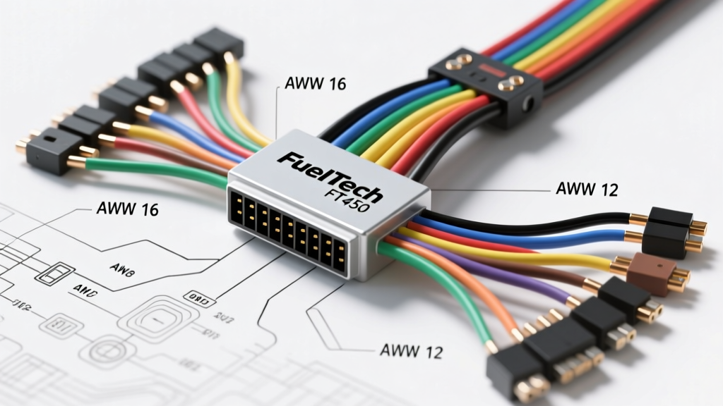
Introduction to the FT450 Harness Architecture
Integrating a standalone engine management system requires a meticulous approach to electrical architecture. The FuelTech FT450 is a formidable motorsport ECU, but its performance is entirely dependent on the integrity of its wiring harness. Unlike OEM systems that rely on pre-packaged, often degraded factory wiring, a custom FT450 installation demands adherence to strict motorsport wiring standards. This advanced technical deep dive explores the FuelTech FT450 wiring diagram, detailing the 80-pin main connector pinout, wire gauge (AWG) specifications, shielding protocols, and critical failure mode prevention.
When constructing or modifying a harness for the FT450, builders must choose between Tefzel (PTFE) insulated wire for custom MIL-SPEC style harnesses or high-quality cross-linked polyethylene (XLPE) wire for standard installations. According to the SAE J1128 High Temperature Automotive Wire Standard, wire insulation must withstand under-hood thermal cycling without becoming brittle or off-gassing corrosive compounds. The FT450 utilizes a single, high-density 80-pin waterproof AMP connector. Mis-pinning or improper crimping of the Deutsch or AMP terminals is the leading cause of ECU communication failure and erratic sensor readings.
Main 80-Pin Connector Pinout & Wire Gauge Specifications
The 80-pin connector is divided into distinct zones: power and ground distribution, low-current sensor inputs, high-current injector/ignition drivers, and CAN-BUS communication. Below is a critical reference table for the primary power, ground, and sensor pins. Always verify against the specific FuelTech Official FT450 Documentation for your exact hardware revision, as minor pinout variations can occur between board versions.
| Pin # | Function | Standard Wire Color | AWG Size | Notes / Requirements |
|---|---|---|---|---|
| 1 | Main ECU Power (Battery +) | Red | 12 AWG | Direct to battery via master relay. Do not daisy chain. |
| 2 | Switched 12V (Ignition) | Red/White | 18 AWG | Triggers ECU wake-up. Must be clean switched 12V. |
| 38 | ECU Main Ground | Black | 12 AWG | Must terminate at engine block or dedicated chassis stud. |
| 39 | Sensor Ground 1 | Black/White | 20 AWG | Dedicated ground for MAP/TPS. Never share with high current. |
| 45 | Crank Sensor Signal (+) | Green | 22 AWG | Shielded pair required for VR sensors. |
| 46 | Crank Sensor Signal (-) | Green/Black | 22 AWG | Shielded pair. Ground shield at ECU connector only. |
| 50 | CAN High | Yellow | 22 AWG | Twisted pair with CAN Low. Requires 120-ohm resistor. |
| 51 | CAN Low | Yellow/Black | 22 AWG | Twisted pair. Keep away from ignition coil power feeds. |
| 70 | Injector 1 (Low Side) | White | 18 AWG | Capable of Low-Z (Peak & Hold) or High-Z saturation. |
| 80 | Ignition Coil 1 (Signal) | Purple | 20 AWG | 5V logic signal for LS-style coils or IGBT igniters. |
Critical Sensor Wiring: Shielding and Signal Integrity
The FT450 processes high-frequency data to calculate fuel delivery and ignition timing within microseconds. Signal degradation from Electromagnetic Interference (EMI) and Radio Frequency Interference (RFI) can cause phantom misfires or erratic timing pulls.
Crank and Cam Sensor Configuration
When wiring Variable Reluctance (VR) sensors, the FT450 relies on a differential input stage. You must use a 22 AWG shielded twisted pair for the signal wires. The critical rule of VR shielding is the 'single-point ground' method. The shield's drain wire must be connected to the sensor ground pin at the ECU's 80-pin connector and left completely floating (unconnected) at the sensor end. Grounding the shield at both ends creates a ground loop, effectively turning the shield into an antenna that amplifies alternator whine and ignition noise directly into the crank signal. For Hall-effect sensors (such as those found on GM LS or Ford Coyote engines), a 20 AWG unshielded twisted triplet (Power, Ground, Signal) is generally sufficient, provided the wiring is routed away from the ignition coil primary feeds.
Wideband O2 and MAP Sensor Integration
The FT450 features internal Wideband O2 controller circuitry. The 4.9 LSU sensor requires dedicated 18 AWG wiring for the heater circuit to prevent voltage drop, which is a common cause of slow O2 response times during cold starts. The MAP sensor wiring must utilize the dedicated Sensor Ground (Pin 39) rather than a chassis ground. Sharing a ground with a high-amperage device like an electric fuel pump will introduce a voltage offset, causing the ECU to read false boost pressure.
Power, Ground, and Relay Control Circuit Design
A robust power distribution module (PDM) or traditional Bosch-style relay network is mandatory. The FT450's main power draw is relatively low (under 3 Amps for the ECU itself), but it acts as the brain for high-current peripherals.
- Master Relay & ECU Relay: Never route the ECU's main 12V feed directly through the ignition switch. Use a heavy-duty 70A master relay to power a fused PDM or relay block. The ECU switched 12V (Pin 2) should trigger a dedicated 30A relay that feeds the ECU's main power (Pin 1). This ensures the ECU receives a clean, uninterrupted voltage supply during cranking, preventing brownouts that corrupt data logs.
- Flyback Voltage Suppression: When the FT450 triggers external relays (e.g., for a cooling fan, fuel pump, or nitrous solenoid), the collapsing magnetic field in the relay coil generates a massive reverse voltage spike (flyback voltage). If the FT450's low-side driver lacks an internal flyback diode, or if the spike exceeds its clamping threshold, the ECU's internal transistor will be destroyed. Always install a 1N4007 flyback diode in reverse parallel across the coil terminals (pins 85 and 86) of any externally triggered automotive relay.
Injector and Ignition Driver Configurations
The FT450 is equipped with highly versatile injector and ignition drivers, but they must be configured correctly in both hardware wiring and software to prevent catastrophic failure.
Low-Z vs High-Z Injectors
If you are running Low-Impedance (Low-Z) injectors (typically 1.5 to 3.0 ohms), the FT450 must be set to 'Peak and Hold' mode in the software. Wiring Low-Z injectors on a High-Z (saturation) setting will draw excessive current, overheating the injector coils and potentially burning out the ECU's internal driver transistors. For Low-Z setups, ensure the 16 AWG injector power feed is sourced from a dedicated relay, as the peak current can exceed 4 Amps per injector during the opening phase.
Ignition Coil Dwell and IGBT Igniters
When wiring smart coils (like GM LS coils with internal igniters), the FT450 sends a 5V logic signal. Ensure the coil power feed is a clean, switched 12V source. If you are running 'dumb' coils (like Ford TFI or external IGBT igniters), the FT450 must handle the dwell current directly or via external high-current igniters. Wiring external igniters requires heavy 14 AWG power and ground wires directly to the battery and engine block, utilizing the FT450 only for the low-current logic trigger signal.
Advanced Troubleshooting: Ground Loops and CAN-BUS Faults
Even with a perfect wiring diagram, real-world installations encounter anomalies. Here is a diagnostic decision tree for common FT450 electrical faults:
- Symptom: Erratic TPS or MAP readings at high RPM.
- Cause: Ground loop or alternator noise bleeding into the 5V reference circuit.
- Fix: Verify that the sensor ground wire is pinned to the ECU and not grounded to the chassis. Check the alternator for bad diodes using an oscilloscope to look for AC ripple on the DC power line.
- Symptom: CAN-BUS drops out or dash freezes under load.
- Cause: EMI interference from ignition wires or missing terminating resistors.
- Fix: Ensure CAN High and CAN Low are twisted at a rate of 3-4 twists per inch. Verify that exactly two 120-ohm resistors exist on the network (one at the ECU, one at the Dash). Route CAN wiring at least 4 inches away from coil-on-plug power feeds.
- Symptom: ECU reboots or logs stop during cranking.
- Cause: Voltage drop on the switched 12V circuit or main power feed.
- Fix: Measure voltage at Pin 1 and Pin 2 during cranking. If voltage drops below 9V, upgrade the cranking battery, clean the main ground stud, or wire a diode/isolation relay to maintain ECU power during starter engagement.
Authoritative References
For continued education on motorsport electrical systems, consult the following resources:
- FuelTech Official FT450 Documentation - Primary source for pinout matrices and software configuration limits.
- SAE J1128 High Temperature Automotive Wire Standard - Governing standards for wire insulation and thermal resistance in engine bays.
- High Performance Academy Wiring Courses - Industry-leading practical guides on MIL-SPEC harness construction, crimping techniques, and EMI mitigation.
Mastering the FuelTech FT450 wiring diagram is not merely about connecting point A to point B; it is about engineering a resilient electrical ecosystem capable of surviving the brutal thermal and electromagnetic environment of a high-performance engine bay. By adhering to strict AWG sizing, shielding protocols, and relay isolation techniques, you ensure the ECU operates flawlessly, translating your tuning efforts into reliable horsepower.